
System for measuring solution concentration by using perturbation method

A solution concentration and measurement system technology, applied in the field of control systems, can solve problems such as limiting the measurement range and need to be improved, and achieve the effects of high measurement reliability, simple structure, and low environmental requirements

Inactive Publication Date: 2012-12-05
TIANJIN UNIV
View PDF8 Cites 14 Cited by
  • Summary
  • Abstract
  • Description
  • Claims
  • Application Information

AI Technical Summary

Problems solved by technology

The indirect measurement method is based on the characteristics of the solution, such as the conductivity of the solution to measure the amount of solute in the solution, but this method can only be applied to electrolyte solutions, which limits its measurement range
[0004] The applicant's previous invention patent application 201210009379.3 provided a microwave resonant cavity sensor and measurement system for measuring solution concentration. The measurement principle of this sensor and measurement system is based on the relationship between the dielectric constant of the solution and the solute content. , can overcome the above-mentioned shortcomings, and has the advantages of simple structure, wide application range, and online measurement. This patent application mainly provides microwave resonant cavity sensors, and the measurement system only provides a basic measurement method. Measurement accuracy needs to be improved

Method used


Image

  • System for measuring solution concentration by using perturbation method
  • System for measuring solution concentration by using perturbation method
  • System for measuring solution concentration by using perturbation method

Examples


Embodiment Construction

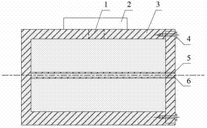
[0018] For more detailed content of the microwave resonant cavity sensor used in the present invention, please refer to the previous patent application 201210009379.3. Combine now figure 1 A brief description of the sensor, the sensor includes a resonant cavity 3; a glass tube 5 is arranged in the middle of the resonant cavity 3, and the inner area 6 of the glass tube is used to place the solution to be measured; a circular hole is opened in the center of the side wall of the resonant cavity 3 1. The resonant cavity is coupled with the rectangular waveguide through the round hole to transmit microwave signals; the positioning screw 4 is used to fix the top cover and the cavity body 3 .

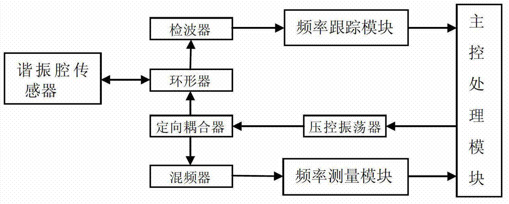
[0019] The microwave signal generated by the microwave source is introduced into the waveguide through the circulator, and then coupled to the resonant cavity through the waveguide transmission. The reflected signal of the resonant cavity is introduced into the detector through the circulator,...


PUM


Abstract

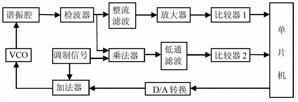
The invention relates to the technical field of solution parameter measurement and relates to a system for measuring a solution concentration by using a perturbation method. The system comprises a microwave resonant cavity sensor, a wave detector, a voltage-controlled oscillator, a frequency tracking module, a frequency measuring module and a main control processing module, wherein frequency modulated signals generated by the voltage-controlled oscillator under the control of the main control processing module are divided into two ways; one way is mixed with local oscillator signals so as to generate difference frequency signals; the other way is led into a waveguide and is transmitted and coupled by the waveguide to be coupled into a resonant cavity; reflecting signal inside the resonant cavity enters the wave detector through a circulator; modulating signals output from the wave detector are transmitted into the frequency tracking module; the frequency tracking module comprises an amplitude discriminating module and a phase discriminating module; the main control processing module is used for controlling the carrier frequency of the voltage-controlled oscillator; the output of the frequency measuring module is accessed to the main control processing module; and the main control processing module obtains the corresponding relationship between a frequency offset and a solution concentration. The system can realize accurate and real-time measurement to the solution concentration.

Description

technical field [0001] The invention relates to a control system for measuring solution concentration based on a perturbation method, which can accurately measure and control the solution concentration, and belongs to the technical field of testing. Background technique [0002] In modern industrial and agricultural production, medicine, chemical industry, food and other fields, there is an urgent need for the detection of a wide range of liquid concentration. It is hoped that a new liquid concentration detection system with simple structure, easy control and accurate measurement will appear. [0003] The solution concentration is calculated according to the content of the solute in the solution. In practical applications, the solution concentration also changes due to the change of the solute amount. The measurement methods of solution concentration are divided into direct measurement and indirect measurement. It is the most basic method to directly extract the solution to...

Claims


Application Information

Patent Timeline
IPC IPC(8): G01N22/00
Inventor 肖夏王洪军
Owner TIANJIN UNIV
Learn More