Calibration source microwave window of microwave radiometer
A microwave radiometer and microwave radiation technology, which is applied in the direction of measuring devices, instruments, and measuring electrical variables, can solve the problems of unsatisfactory microwave window filling uniformity, poor versatility and flexibility, and large emissivity measurement errors. Achieve good heat insulation effect, flexible combination, and reduce measurement error
- Summary
- Abstract
- Description
- Claims
- Application Information
AI Technical Summary
Problems solved by technology
Method used
Image

Examples
Embodiment Construction
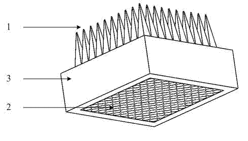
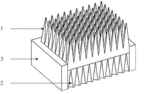
[0016] A calibration source microwave window for a microwave radiometer, comprising: a tapered tapered array 1 , a tapered hollow tapered array 2 , and a fastening frame 3 .
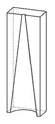
[0017] The tapered hollow gradient array 2 is composed of 2×n subunits. The sub-unit is conical or square-conical, and is made of polystyrene with the same cubic shape. On the sub-unit, there is a semi-hollow structure that is complementary to the conical tip of the microwave radiator. The conical tip of the microwave radiator is Half of the split is placed in it. The two subunits are put together to form a complete complementary structure with a conical wedge of a microwave radiator, and they are in close contact. The conical hollow structure formed by putting together the two subunits is in the shape of a cone or a pyramid.
[0018] The tapered gradient array 1 is integrally formed from a whole piece of polystyrene, and its outer contour is rectangular. One side of the tapered array faces outward, a...
PUM
 Abstract
Description
Claims
Application Information
 - R&D
- Intellectual Property
- Life Sciences
- Materials
- Tech Scout
- Unparalleled Data Quality
- Higher Quality Content
- 60% Fewer Hallucinations
Browse by: Latest US Patents, China's latest patents, Technical Efficacy Thesaurus, Application Domain, Technology Topic, Popular Technical Reports.
© 2025 PatSnap. All rights reserved.Legal|Privacy policy|Modern Slavery Act Transparency Statement|Sitemap|About US| Contact US: help@patsnap.com