Guide wire
A technology of guide wire and protrusion, applied in the direction of catheter, guide wire, etc., can solve the problem of rolling up
- Summary
- Abstract
- Description
- Claims
- Application Information
AI Technical Summary
Problems solved by technology
Method used
Image
Examples
no. 1 Embodiment approach
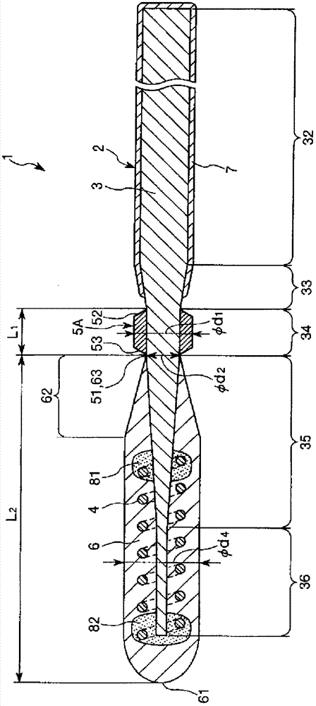
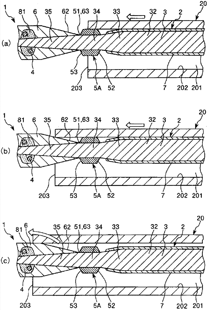
[0033] figure 1 It is a longitudinal sectional view showing the first embodiment of the guide wire of the present invention, figure 2 yes means figure 1 Longitudinal sectional view of the guide wire shown in use. In addition, in the following, for the convenience of explanation, the figure 1 and figure 2 in (later mentioned Figure 3 ~ Figure 7 Similarly) the right side is called "basal end", and the left side is called "front end". In addition, in each figure, for easy understanding, the longitudinal direction of the guide wire is shortened, and the width direction of the guide wire is exaggerated and schematically shown, and the ratio of the longitudinal direction and the width direction is different from the actual one.
[0034] Figure 1 ~ Figure 3 The shown guide wire 1 is a catheter guide wire used for insertion into the lumen 201 of a catheter 20 (including an endoscope), and the guide wire includes: a long guide wire body 2; a helical coil 4; and a front end T...
no. 2 Embodiment approach
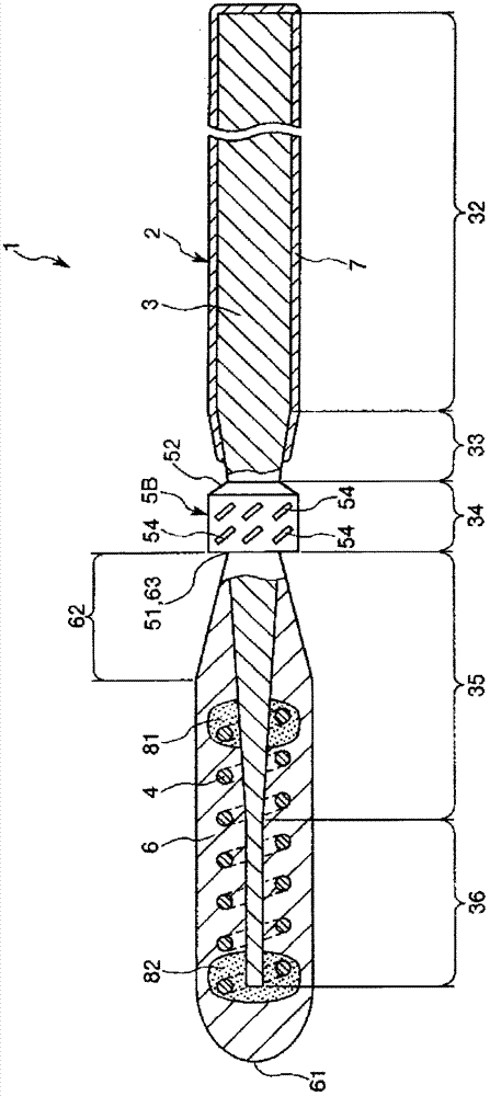
[0075] image 3 It is a partial vertical cross-sectional side view showing a second embodiment of the guide wire of the present invention.
[0076] Hereinafter, a second embodiment of the guide wire of the present invention will be described with reference to this figure, but the description will focus on the differences from the above-mentioned embodiment, and the description of the same items will be omitted.
[0077] This embodiment is the same as the above-mentioned first embodiment except that the structure of the protruding member is different.
[0078] exist image 3 In the shown guide wire 1 , a plurality of grooves (recesses) 54 are formed on the outer peripheral portion of the protruding member 5B. Moreover, each groove 54 is inclined relative to the longitudinal direction of the guide wire. In addition, each groove 54 is preferably a slit penetrating through the wall portion of the protruding member 5B.
[0079] By forming such grooves 54 , the protruding member...
no. 3 Embodiment approach
[0083] Figure 4 It is a partial vertical cross-sectional side view showing a third embodiment of the guide wire of the present invention.
[0084] Hereinafter, a third embodiment of the guide wire of the present invention will be described with reference to this figure, but the description will focus on the differences from the above-mentioned embodiment, and the description of the same items will be omitted.
[0085] This embodiment is the same as the above-mentioned first embodiment except that the structure of the protruding member is different.
[0086] exist Figure 4 In the shown guide wire 1 , the protruding member 5C is constituted by a coil in which a wire 55 is wound helically around the axis of the core wire 3 . As a result, the protruding member 5C itself becomes a flexible member, so that the followability of the guide wire 1 , especially the protruding member 5C to a curved living body lumen is improved.
[0087] In addition, the protruding part 5C is in Fi...
PUM
| Property | Measurement | Unit |
|---|---|---|
| Thickness | aaaaa | aaaaa |
Abstract
Description
Claims
Application Information
 - R&D
- Intellectual Property
- Life Sciences
- Materials
- Tech Scout
- Unparalleled Data Quality
- Higher Quality Content
- 60% Fewer Hallucinations
Browse by: Latest US Patents, China's latest patents, Technical Efficacy Thesaurus, Application Domain, Technology Topic, Popular Technical Reports.
© 2025 PatSnap. All rights reserved.Legal|Privacy policy|Modern Slavery Act Transparency Statement|Sitemap|About US| Contact US: help@patsnap.com


