Thermal vacuum outgassing testing apparatus

A test device and thermal vacuum technology, applied in the direction of measurement device, material thermal analysis, material thermal conductivity, etc., can solve the problems of difficult to clear the root around the pit, affect the heat transfer effect, affect the temperature of the collecting plate, etc., so as to reduce the assembly error. , to ensure the design accuracy, to avoid the effect of mutual interference

Active Publication Date: 2012-12-12
VACREE TECH +1
View PDF6 Cites 3 Cited by
  • Summary
  • Abstract
  • Description
  • Claims
  • Application Information

AI Technical Summary

Problems solved by technology

The disadvantages of the prior art are: the vacuum cover is a slender structure, the vacuum pumping system is located at the bottom of the vacuum cover, and the suction port is small, which is not conducive to the establishment of high vacuum; the sample tank is a vertical structure of 650×50×25 , and the sample tank needs to be equipped with a heating device, the distance between the installed sample tank and the collection box is only 0.75mm, and the processing and positioning accuracy are difficult to guarantee
The collecting plate is fixed by magnetic attraction, the magnet is fixed on the cooling plate by screws, and the corresponding cooling plate is provided with step holes, which reduces the contact area between the collecting plate and the cooling plate, which affects the heat transfer effect
Limited by the area of ​​the magnet, the magnet has a limited area of ​​action on the collecting plate, and the collecting plate is a thin plate with a thickness of only 0.65, which affects the degree of bonding between the collecting plate and the cooling plate, which in turn affects the temperature of the collecting plate and affects the test results the accuracy of
There are strict coaxiality requirements between the collecting plate, the collecting box and the air outlet of the sample tank. It is difficult to locate the collecting plate in this technical route. Clear the root, and then affect the bonding degree of the collecting plate and the cooling plate

Method used


Image

  • Thermal vacuum outgassing testing apparatus
  • Thermal vacuum outgassing testing apparatus
  • Thermal vacuum outgassing testing apparatus

Examples


Embodiment Construction

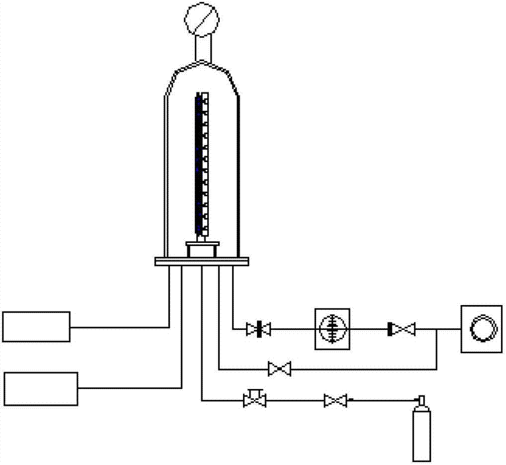
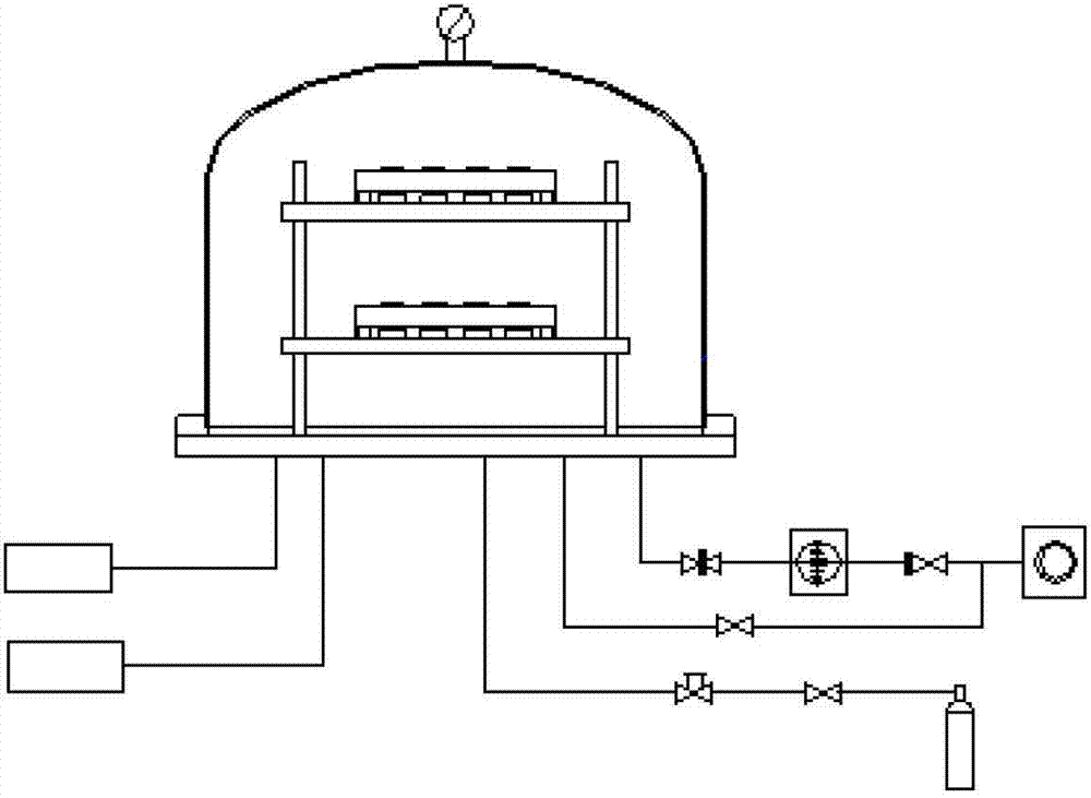
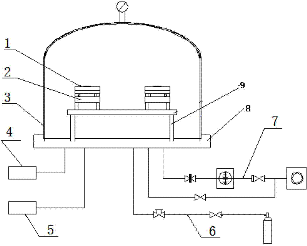
[0019] Such as image 3 , 4 As shown, a thermal vacuum outgassing test device includes an operating table 8 and a vacuum cover 3 installed above the operating table 8, and a heating plate temperature control system 4 and a cooling plate temperature control system are respectively arranged below the operating table 8 5. The inflatable device 6 and the vacuum system 7, the temperature control system accurately controls the temperature of the heating plate 1 and the cooling plate 2 respectively, the vacuum system 7 provides the vacuum degree required for the test, and the inflatable device 6 is injected into the vacuum cover 3 after the test Refilling with dry and clean nitrogen, there is an operating device in the vacuum cover 3, the operating device includes two identical devices and is distributed on the same operating plate 8 in a double-row parallel structure, and the cooling plate 2 The heating plate 1 is supported on the cooling plate 2 by a heat insulating support mechan...


PUM

PropertyMeasurementUnit
diameteraaaaaaaaaa
thicknessaaaaaaaaaa

Abstract

The invention discloses a thermal vacuum outgassing testing apparatus. The apparatus mainly comprises a vacuum cover (including an outgassing collecting device and a sample groove, etc.), a vacuum pumping system, a high guarantee system, a low temperature guarantee system, a temperature vacuum degree measurement and control system and an auxiliary system. The vacuum pumping system provides vacuum degree required by the testing apparatus; and the high temperature guarantee system and the low temperature guarantee system are respectively a high temperature device and a low temperature circulating device, and provide a sample heating temperature of 125+/-1 DEG C and a temperature of 25+/-1 DEG C required by a collecting plate. The apparatus provided by the invention guarantees effective conduction of cooling capacity between the collecting plate and a cooling plate; and the collecting plate and the cooling plate have same and uniform temperature, and employ a double-row parallel structure to avoid mutual interference of the released gas. The operation is quick and convenient, so as to improve the accuracy of the test result.

Description

technical field [0001] The invention relates to a test device, in particular to a thermal vacuum outgassing test device. Background technique [0002] The thermal vacuum outgassing test device in the prior art adopts two rows of vertical structure test devices, such as figure 1 As shown, each row of devices is composed of a sample tank (heater), a cooling plate, a collection box, and a collection plate. Each row of devices has 12 sample slots, corresponding to 12 collection plates and collection boxes. The test device is installed on the bottom plate of the vacuum system with a diameter of 260mm bell jar, adopts a dedicated through-type ring base, and is supported by the bottom plate. The connection structure of the collection box, the collection plate and the cooling plate is the key to the test equipment. The collecting box is composed of a space formed by a partition and a cooling plate; screws are welded at the bottom of the collecting plate, and are connected wit...

Claims


Application Information

Patent Timeline
Patent Type & Authority Applications(China)
IPC IPC(8): G01N25/00G01N25/18
Inventor 孙志和章学华汪澎石国丽张宗峰丁怀况韩锐马学焕沈丽萍
Owner VACREE TECH
Why Eureka
Try Eureka