
Capacitive touch screen and touch device with same

A technology of capacitive touch screen and array, applied in the direction of electrical digital data processing, input/output process of data processing, instruments, etc., can solve problems such as interference, positioning error, small capacitance change of capacitive sensor, etc., to improve sensing sensitivity and linearity Accurate calculation of degrees and coordinates, and the effect of improving positioning accuracy

Inactive Publication Date: 2012-12-12
BYD CO LTD
View PDF3 Cites 6 Cited by
  • Summary
  • Abstract
  • Description
  • Claims
  • Application Information

AI Technical Summary

Problems solved by technology

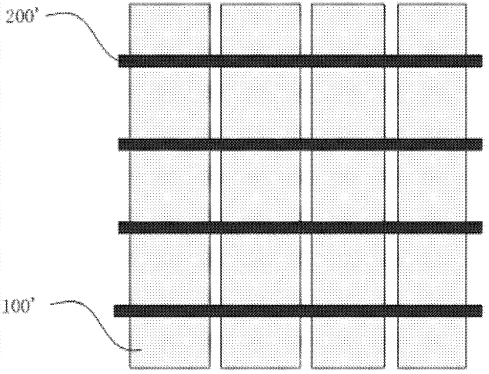
[0004] There is such a problem in the arrangement of the signal detection end and the excitation signal supply end of the existing mutual capacitive touch screen: when the touch object (such as a finger) is between the two signal detection ends, or when only close to one of the excitation signal supply ends, Another excitation signal supply end will only have a slight induction, so the induction signal will not form a stable and accurate linear change, resulting in positioning errors
Although the cost of double-layer mutual capacitive touch screen is lower than that of touch panel with four-layer or three-layer circuit structure, it still cannot meet the price requirements of users
Although the cost of a single-layer mutual capacitive touch screen is very low, the output capacitance of the capacitive sensor changes very little, and there are stray capacitances in it, and the stray capacitance will change with many factors such as temperature, position, and internal and external electric field distribution. Interfering or even submerging the measured capacitance signal, making it impossible to sense the touch and locate the touch point

Method used


Image

  • Capacitive touch screen and touch device with same
  • Capacitive touch screen and touch device with same
  • Capacitive touch screen and touch device with same

Examples


Embodiment Construction

[0020] Embodiments of the present invention are described in detail below, examples of which are shown in the drawings, wherein the same or similar reference numerals designate the same or similar elements or elements having the same or similar functions throughout. The embodiments described below by referring to the figures are exemplary only for explaining the present invention and should not be construed as limiting the present invention.

[0021] In describing the present invention, it should be understood that the terms "longitudinal", "transverse", "upper", "lower", "front", "rear", "left", "right", "vertical", The orientation or positional relationship indicated by "horizontal", "top", "bottom", "inner", "outer", etc. are based on the orientation or positional relationship shown in the drawings, and are only for the convenience of describing the present invention and simplifying the description, rather than Nothing indicating or implying that a referenced device or elem...


PUM


Abstract

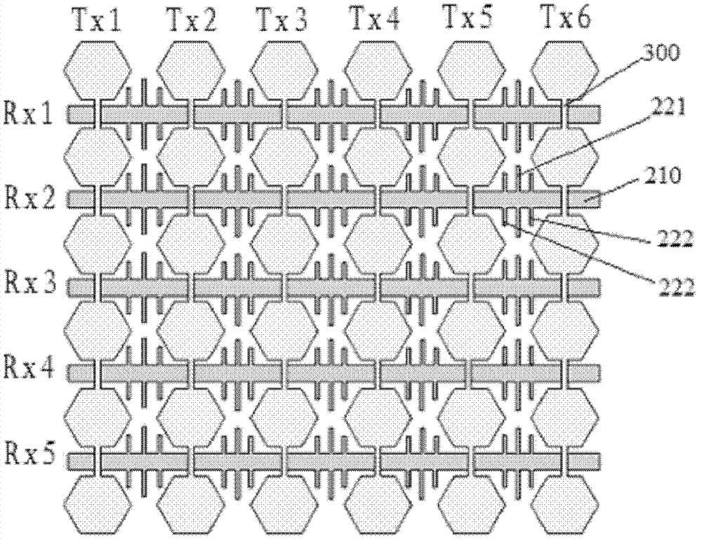
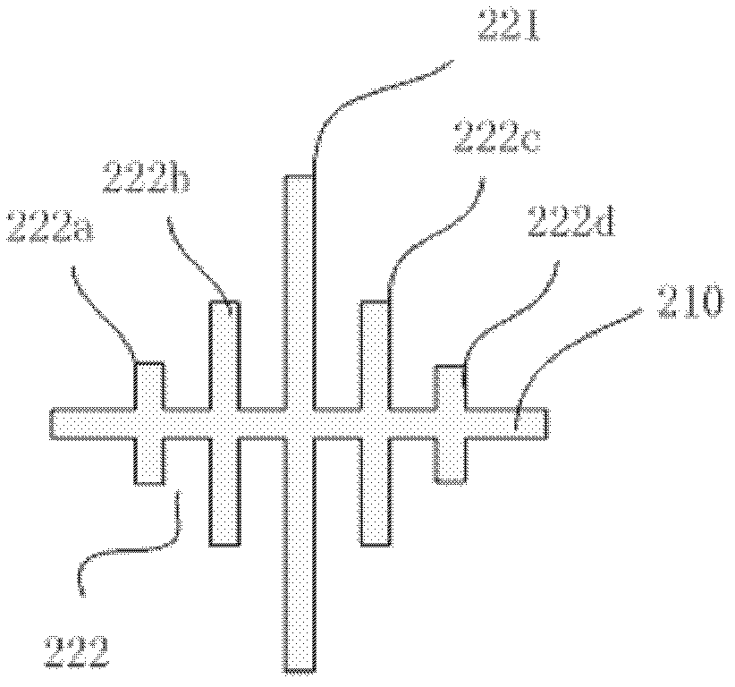
The invention provides a capacitive touch screen which comprises a transparent base plate, a first conducting array and a second conducting array. The first conducting array is arranged on the transparent base plate and comprises a plurality of drive components for providing drive signals, and the drive components are of hexagon. The second conducing array has a scheduled angle with the first conducting array and comprises a plurality of receiving components for receiving the drive signals provided by the plurality of drive components. The receiving components comprise bodies and a plurality of cantilever portions extending outward perpendicularly from the bodies, and a scheduled distance is arranged between the adjacent cantilever portions. The invention further provides a touch device with the capacitive touch screen. The shapes of the drive components and the receiving components are changed, the distance between the receiving components and the drive components is enlarged, and therefore mutual capacitance variation is improved, and induction sensitivity and linearity are improved.

Description

technical field [0001] The invention relates to the technical field of touch control, in particular to an improved capacitive touch screen and a touch device with the capacitive touch screen. Background technique [0002] The touch screen has been widely used in various electronic products due to its small mechanical loss and small size. Common touch screens have self-capacitance and mutual-capacitance printed circuit board structures. Self-capacitance can only achieve single-point touch, if double-point touch will produce "ghost points". Therefore, the application of the mutual capacitance printed circuit board structure is more extensive. [0003] figure 1 It is a plan view of an existing double-layer mutual capacitance printed circuit board structure. The horizontal black bar is the capacitive signal detection terminal 200' on the top layer, and the vertical direction is the excitation signal supply terminal 100', and the two are perpendicular to each other. When the...

Claims


Application Information

Patent Timeline
IPC IPC(8): G06F3/044
Inventor 王波李振刚黄臣杨云
Owner BYD CO LTD
Learn More