Method for reducing positioning torque of magnetic-flux switching permanent magnet motor

A technology of magnetic flux switching and permanent magnet motor, which is applied to the static parts of the magnetic circuit, the shape/style/structure of the magnetic circuit, etc., which can solve the problems of difficult starting of the motor, increase the manufacturing cost of the motor, torque ripple, etc., and achieve the material cost drop, high power density, and the effect of broadening the output power

Active Publication Date: 2012-12-12
CHINA ELECTRIC POWER RES INST +1
View PDF2 Cites 4 Cited by
  • Summary
  • Abstract
  • Description
  • Claims
  • Application Information

AI Technical Summary

Problems solved by technology

This torque always exists in the permanent magnet motor, regardless of whether the motor is energized or not. Excessive peak-to-peak values ​​will not only cause difficulties in starting the motor, but also cause large torque ripples during the operation of the motor, thereby limiting its Therefore, it is of great significance and practical value to use effective methods to reduce the positioning torque of flux switching permanent magnet motors.
[0005] The traditional methods of reducing the positioning torque of permanent magnet motors include rotor skew, stator chute, fractional slot structure, combination optimization of pole arc coefficients, asymmetric placement of permanent magnets, and pole shape optimization, etc. These methods will have different effects on the performance of the motor degree of influence, but also increase the manufacturing cost of the motor

Method used


Image

  • Method for reducing positioning torque of magnetic-flux switching permanent magnet motor
  • Method for reducing positioning torque of magnetic-flux switching permanent magnet motor
  • Method for reducing positioning torque of magnetic-flux switching permanent magnet motor

Examples


Embodiment 1

[0033] The invention is used for axial magnetic flux switching permanent magnet motors.

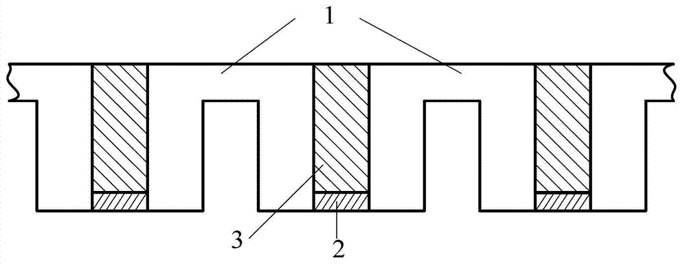
[0034] The motor is three-phase 12 / 10 poles, consisting of two outer stators of the same structure and a rotor. Each stator is composed of 12 "U"-shaped magnetic cores, 12 permanent magnets and 12 coils; each coil is wound on the teeth of two adjacent "U"-shaped magnetic cores, and permanent magnets are embedded in the middle. The magnets are alternately magnetized tangentially. The magnetization directions of the facing permanent magnets on the stators on both sides are opposite. Stator winding adopts concentrated winding. The rotor has a total of 10 teeth, which are evenly arranged on the outer circumference of the non-conductive ring of the rotor.

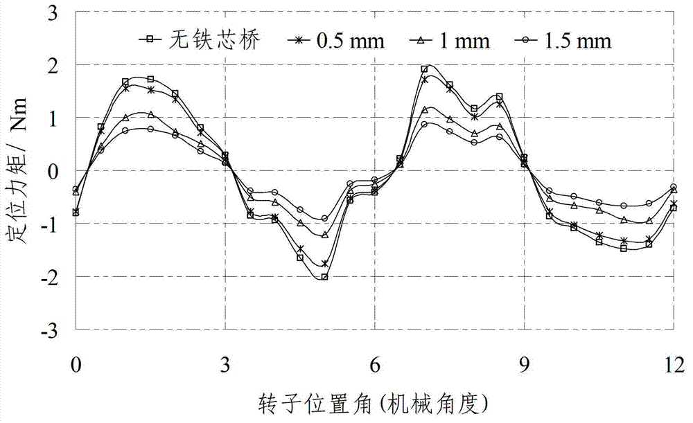
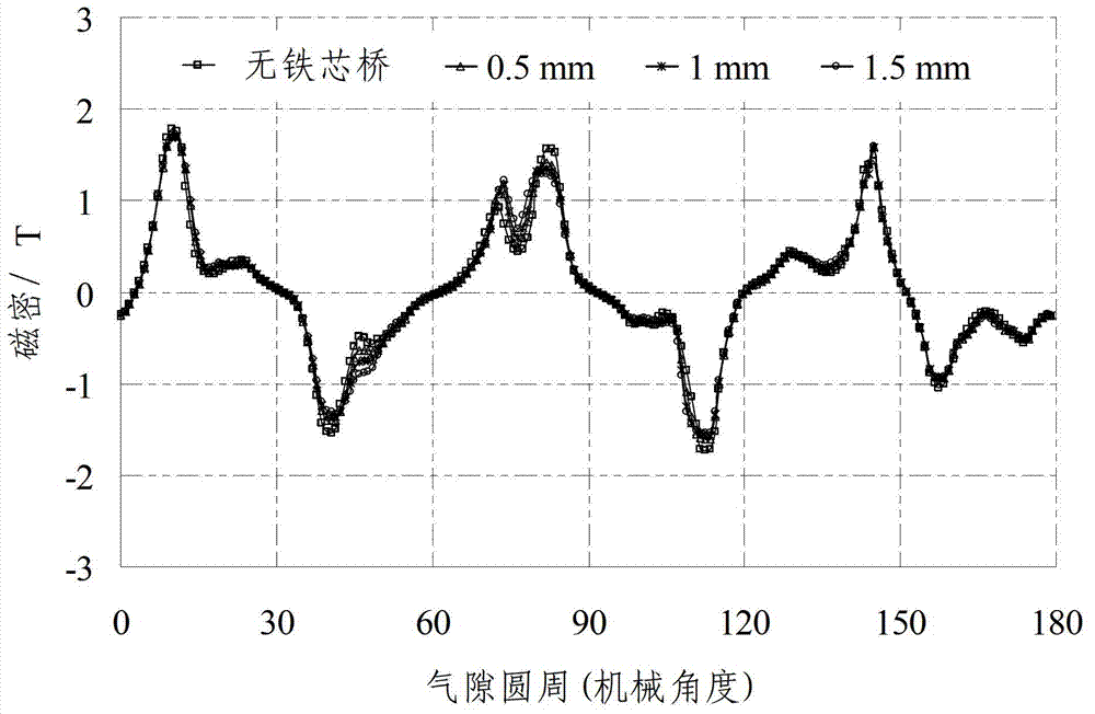
[0035] According to the description in the specific embodiment, the iron core bridge 2 is added between the adjacent stator iron cores 1 of the three-phase 12 / 10 pole magnetic flux switching permanent magnet motor, and the thickness of t...


PUM

PropertyMeasurementUnit
thicknessaaaaaaaaaa
thicknessaaaaaaaaaa
thicknessaaaaaaaaaa

Abstract

The invention provides a method for reducing the positioning torque of a magnetic-flux switching permanent magnet motor, comprising the following steps: arranging an iron core bridge between stator iron cores of the magnetic-flux switching permanent magnet motor; arranging a permanent magnet in a groove which is formed by adjacent stator iron cores and the iron core bridge, and setting the initial thickness of the iron core bridge as the length of the air gap of the magnetic-flux switching permanent magnet motor; determining the performance parameter involved in the iron core bridge thickness optimization process of the magnetic-flux switching permanent magnet motor; and optimizing and determining the thickness of the iron core bridge. The method is simple and efficient, the project is easy to implement, the thickness of the iron core bridge can be optimized by adopting the finite element method, the positioning torque of the magnetic-flux switching permanent magnet motor is reduced effectively, and the other performances of the magnetic-flux switching permanent magnet motor are hardly affected.

Description

technical field [0001] The invention belongs to the technical field of permanent magnet motors, and in particular relates to a method for reducing the positioning torque of a magnetic flux switching permanent magnet motor. Background technique [0002] Compared with electric excitation motors, permanent magnet motors have significant advantages such as small size, light weight, and high efficiency; because they do not require excitation windings and DC excitation power supplies, the collector rings and brush devices that are prone to problems are eliminated, and the structure is simple. Reliable operation, so it is being gradually popularized and applied in wind power generation, small hydropower generation, and small internal combustion engine power generation, especially direct-drive wind power generation using permanent magnet generators has become quite attractive today. In addition, my country is rich in rare earth resources, and the scientific research level of rare ea...

Claims


Application Information

Patent Timeline
Patent Type & Authority Applications(China)
IPC IPC(8): H02K1/06H02K1/17
Inventor 张磊朱凌志赵大伟
Owner CHINA ELECTRIC POWER RES INST
Why Eureka
Try Eureka