Position sensor

A sensor and displacement technology, applied in the direction of converting sensor output, using electric/magnetic devices to transmit sensing components, instruments, etc., can solve the problems of oscillating circuit 101 error increase and error variation, etc., and achieve the goal of reducing error and its variation Effect

Inactive Publication Date: 2012-12-12
PANASONIC INTELLECTUAL PROPERTY MANAGEMENT CO LTD
View PDF7 Cites 8 Cited by
  • Summary
  • Abstract
  • Description
  • Claims
  • Application Information

AI Technical Summary

Problems solved by technology

[0012] Thus, in the conventional example, there is a problem that the error of the oscillation frequency of the oscillation circuit 101 relative to the resonance frequency of the resonance circuit 100 becomes large depending on the setting of the negative conductance Gosc of the oscillation circuit 101 and the ambient temperature of the oscillation circuit 101. or the error will change

Method used


Image

  • Position sensor
  • Position sensor
  • Position sensor

Examples


Embodiment Construction

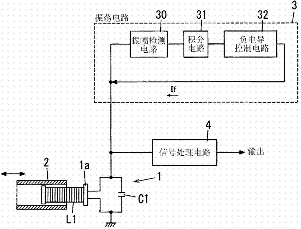
[0029]Embodiments of the present invention will be described in detail below with reference to the drawings constituting this specification. In all the drawings, the same symbols are assigned to the same or similar parts, and repeated description thereof will be omitted. Such as figure 1 As shown, the position sensor according to this embodiment includes a resonance circuit 1, a detection body 2, an oscillation circuit 3, and a signal processing circuit 4. The oscillation circuit 3 includes an amplitude detection circuit 30, an integration circuit 31, a negative conductance control circuit 32, and an arithmetic operation circuit 30. amplifier (differential amplifier) ​​OP1. In addition, the oscillation circuit 3 and the signal processing circuit 4 are integrated in an integrated circuit such as a monolithic IC, for example. In addition, a negative feedback loop is formed by the amplitude detection circuit 30, the integration circuit 31, the negative conductance control circ...


PUM


Abstract

Provided is a position sensor that is equipped with a detector (2), an oscillation circuit (3), a signal processing circuit (4), and a resonance circuit (1) comprising a detection coil (L1) and a capacitator (C1), wherein the oscillation circuit (3) forms a negative feedback loop from: an amplitude detection circuit (30) that detects the amplitude of an oscillation signal output by the resonance circuit (1); an integrating circuit (31) that outputs a signal in response to the finite difference between a given reference voltage and the amplitude value of the oscillation signal detected by the amplitude detection circuit (30); a negative conductance control circuit (32) that, on the basis of the output of the integrating circuit (31), controls the negative conductance of the oscillation circuit (3) so that the given reference voltage and the amplitude value of the oscillation signal match; and an operational amplifier (OP1) that adjusts so as to equalize the oscillation voltage (VLC) of the resonance circuit (1), and the applied voltage (VR) of the negative conductance control circuit (32).

Description

technical field [0001] The present invention relates to a position sensor for detecting displacement of an object. Background technique [0002] Conventionally, various position sensors for detecting displacement of an object (eg, rotation amount, rotation angle, or rotation position of a rotating object) have been provided. For example, there is a position sensor disclosed in Patent Document 1. The displacement sensor (position sensor) described in this patent document 1 includes: a detection coil wound on a cylindrical core made of a non-magnetic material; and a cylindrical conductor disposed near the inside or outside of the detection coil. , capable of shifting in the axial direction of the detection coil. Furthermore, an oscillation signal whose frequency corresponds to the inductance of the detection coil which varies according to the distance between the detection coil and the conductive body and the electrostatic capacity of a capacitor connected in parallel to the ...

Claims


Application Information

Patent Timeline
Patent Type & Authority Applications(China)
IPC IPC(8): G01D5/20G01D5/243
CPCG01D5/2013G01D5/20G01D5/243
Inventor 丹羽正久冈田邦孝
Owner PANASONIC INTELLECTUAL PROPERTY MANAGEMENT CO LTD
Why Eureka
Try Eureka