Antenna device and communication device

A technology for an antenna device and a communication device, which is applied to resonant antennas, near-field transmission systems using transceivers, electrical components, etc., can solve problems such as deterioration of production efficiency, complicated processes, and addition of components or processes, and achieve good connectivity, The effect of high production efficiency

Inactive Publication Date: 2012-12-12
DEXERIALS CORP
View PDF7 Cites 6 Cited by
  • Summary
  • Abstract
  • Description
  • Claims
  • Application Information

AI Technical Summary

Problems solved by technology

[0007] However, as in the communication device described in Patent Document 1, the transceiver circuit assembled by surface mounting and the three-dimensionally configured high-frequency coupler are arranged on the same printed circuit board. From the viewpoint of the mounting process, there are complicated steps and problems. It is also necessary to pay attention to the problem of deterioration of production efficiency in operation
In addition, for the communication device described in Patent Document 1, a high-frequency coupler is separately produced, and the coupling electrode is arranged more freely without being restricted by the arrangement position of the transceiver circuit. Connecting to the transceiver circuit requires a connection device such as a connection cable in addition to the printed circuit board, and there is a problem of adding parts or processes.

Method used


Image

  • Antenna device and communication device
  • Antenna device and communication device
  • Antenna device and communication device

Examples


no. 1 approach

[0033] As an antenna device incorporated into such a communication system 100, for example figure 2 The high-frequency coupler 110 of the first embodiment shown will be described.

[0034] That is, the high-frequency coupler 110 includes: a flexible printed board 1 ; a coupling electrode 8 ; and an electrode post 7 that electrically connects the signal line 3 formed on the flexible printed board 1 and the coupling electrode 8 .

[0035] The flexible printed circuit board 1 is a flexible double-sided printed circuit board in which copper foil is arranged on both sides of a substrate 4 functioning as a dielectric, and the conductive layer on one surface is grounded 2, and the conductive layer on the other surface is passed through The patterning process forms the signal line 3 .

[0036] The base material 4 of the flexible printed substrate 1 is a material with better dielectric properties than the conductive layer, for example, a flexible dielectric material with a thickness...

no. 2 approach

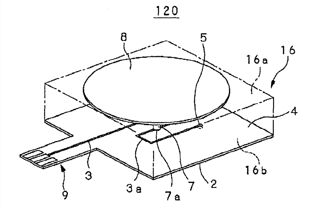
[0068] Next, as another embodiment of the antenna device to which the present invention is applied, for example Figure 11 The configuration of the high-frequency coupler 120 in the second embodiment shown will be described.

[0069] The high-frequency coupler 120 is similar to the high-frequency coupler 110 in the above-mentioned first embodiment, and includes a flexible printed circuit board 1, a coupling electrode 8, and a circuit that electrically connects the signal line 3 formed on the flexible circuit board 1 and the coupling electrode 8. Electrode column 7. In addition, the high-frequency coupler 120 includes an upper substrate 16 as a fixing member that holds the coupling electrode 8 .

[0070] Here, in the high-frequency coupler 110 in the first embodiment, since the coupling electrode 8 is held by the electrode column 7, the strength is weak, and care must be taken when moving the finished product. On the other hand, the high-frequency coupler 120 in the present em...


PUM


Abstract

Disclosed is an antenna device wherein a coupling electrode can be freely disposed without being limited by the position where a transmitting/receiving circuit maintaining excellent connectivity is disposed, while achieving a high production efficiency. The antenna device is provided with: a printed board wherein ground (2) is formed on one surface, and a signal line (3) having signals transmitted thereto is formed on the other surface, with a base material (4) between the ground and the signal line; the coupling electrode (8), which is composed of a conductor having substantially a flat surface, and which performs communication by being coupled, by electromagnetic field coupling, with the electrode of other antenna device disposed on a position facing the coupling electrode; and an electrode post (7) which electrically connects together the signal line (3) formed on the printed board, and the coupling electrode (8) by having the signal line and the printed board at a predetermined interval in the direction of the thickness of the printed board. A connecting terminal section (9) that can be electrically connected with the transmitting/receiving device, which performs signal transmission/reception processing, is formed on one end of the signal line (3), and at least a terminal forming section (1a), which has the connecting terminal section (9) formed thereon, has flexibility in the printed board.

Description

technical field [0001] The present invention relates to an antenna device for performing information communication through electromagnetic field coupling between a pair of opposing electrodes, and a communication device incorporating the antenna device. [0002] This application claims priority on the basis of Japanese Patent Application No. Japanese Patent Application No. 2010-021518 for which it applied in Japan on February 2, 2010, and takes in this application by referring this application. Background technique [0003] In recent years, systems for wirelessly transmitting data such as music and images between electronic devices such as computers and small mobile terminals have been developed without cables or media. Among such wireless transmission systems, there is a wireless transmission system capable of high-speed transmission of up to about 560 Mbps at a short distance of several centimeters. Among such transmission systems capable of high-speed transmission, Trans...

Claims


Application Information

Patent Timeline
Patent Type & Authority Applications(China)
IPC IPC(8): H04B5/02
CPCH04B5/00H01Q9/0407
Inventor 久村达雄
Owner DEXERIALS CORP
Why Eureka
Try Eureka