Jacking ladle car and applications thereof in vacuum circulating degasification refining method

A ladle trolley and jacking technology, applied in the direction of lifting device, can solve the problems of complex process equipment, poor overall stability, large lifting stroke, etc., and achieve the effect of simplifying process equipment, convenient maintenance, and simplified operation

Inactive Publication Date: 2012-12-19
BAOSTEEL ENG & TECH GRP
View PDF5 Cites 5 Cited by
  • Summary
  • Abstract
  • Description
  • Claims
  • Application Information

AI Technical Summary

Problems solved by technology

In the current RH process layout, the RH ladle car runs to the RH vacuum treatment position after the ladle accepts the full ladle, and the hydraulic system in the hydraulic chamber drives the large-scale hydraulic jacking or lifting equipment to lift the ladle or the ladle car and arrive at it. The disadvantage of vacuum treatment of molten steel at the set position is that the process equipment is complicated, the lifting stroke is large, the lifting fulcrum is at the bottom of the ladle, and the overall stability of the ladle after jacking is poor. A special large-scale equipment and hydraulic system are required to realize the lifting of the ladle. It also requires a hydraulic station building, complex pipelines for conveying hydraulic oil, and a complex hydraulic system for ladle lifting control. The hydraulic system includes: 4 main pumps, 3 control pumps, 3 circulating pumps and hydraulic control valves and instruments. Dig a deep foundation pit of -8~10m underground to arrange jacking equipment, or raise the process platform to install lifting hydraulic cylinder equipment, and the synchronization of multiple hydraulic cylinders needs to be considered
And once the upper part of the ladle wears steel, the molten steel will directly burn the ladle jacking device or lifting device and hydraulic cylinder

Method used


Image

  • Jacking ladle car and applications thereof in vacuum circulating degasification refining method
  • Jacking ladle car and applications thereof in vacuum circulating degasification refining method
  • Jacking ladle car and applications thereof in vacuum circulating degasification refining method

Examples


Embodiment 1

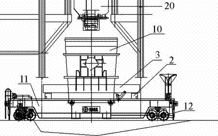
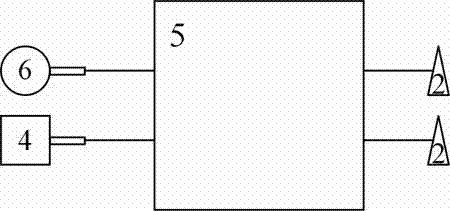
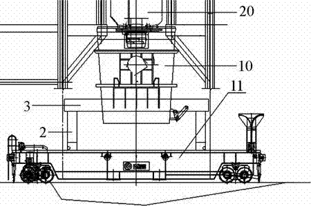
[0019] A jack-up type ladle trolley includes a car body 11, a wheel group 12, an electric jack 2, a support frame 3, an electric motor 4, a double-input double-output reducer 5 and an air motor 6, such as figure 1 and figure 2 As shown, the specific structure is: the four corners of the bottom of the vehicle body 11 are respectively provided with wheel sets 12, there are four electric jacks 2, the bases of the electric jacks 2 are respectively fixed on the four corners of the upper part of the vehicle body 11, the support frame 3 has four The lower part of the corner is provided with a pit, and the moving rods of each electric jack 2 are respectively fixed in the pits in the lower part of the four corners of the support frame 3; there are two motors 4 and two double-input double-output reducers 5, each with two The input double output reducer 5 has two input shafts and two output shafts. The rotating shaft of each motor 4 is connected to one input shaft of a double input doub...


PUM


Abstract

The invention relates to the field of steel refining by vacuum treatment, and particularly relates to a jacking ladle car and applications of the jacking ladle car in a vacuum circulating degasification refining method. The jacking ladle car comprises a car body (11) and a wheel group (12). The jacking ladle car is characterized by also comprising electric jacks (2), a support frame (3), motors (4), a double-input double-output speed reducer (5) and a pneumatic motor (6); bases of the electric jacks (2) are respectively fixed at the four corners at the upper part of the car body (11); movable rods of each electric jack (2) are respectively fixed into pits at the lower parts of the four corners of the support frame (3); and a rotating shaft of each motor (4) is connected with an input shaft of the double-input double-output speed reducer (5), and two output shafts of each double-input double-output speed reducer (5) are connected with one electric jack (2). The jacking ladle car is simple in structure, convenient to manufacture, safe and reliable.

Description

technical field [0001] The invention relates to the field of refining steel by vacuum treatment, in particular to a jack-up ladle trolley and its application in a vacuum cycle degassing refining method. Background technique [0002] Vacuum circulating degassing refining (referred to as RH) is a secondary refining process for molten steel used to produce high-quality steel. During refining, the whole metallurgical reaction of molten steel is carried out in a vacuum tank with refractory lining. The lower part of the vacuum tank is two dipping pipes with refractory lining, and the upper part is equipped with hot bending pipes. The pumped gas is discharged to the outside of the workshop from the hot elbow through the gas cooler to the vacuum pump system. The advantages of molten steel treated with RH are: the alloy basically does not react with the slag, the alloy is directly added to the molten steel, and the yield is high; the molten steel can be quickly and uniformly mixed; ...

Claims


Application Information

Patent Timeline
Patent Type & Authority Applications(China)
IPC IPC(8): B66F11/00C21C7/10C21C7/072
Inventor 邱勤李维强韩鹏郑海明刘景春谢永登
Owner BAOSTEEL ENG & TECH GRP
Why Eureka
Try Eureka