Reflective heated waste rubber and waste plastic thermal cracking device

A waste rubber and waste plastic technology, which is applied in plastic recycling, preparation of liquid hydrocarbon mixture, petroleum industry, etc., can solve the problems of low cracking efficiency, high temperature, high labor intensity, etc., to prolong the retention time and equipment The effect of low manufacturing cost and low labor intensity

Inactive Publication Date: 2012-12-19
SHANGQIU SIHAI MACHINERY EQUIP MFG
View PDF5 Cites 4 Cited by
  • Summary
  • Abstract
  • Description
  • Claims
  • Application Information

AI Technical Summary

Problems solved by technology

[0003] Pyrolysis equipment also emerged as the times require, with a wide variety, but most of them are intermittently produced pyrolysis equipment, with low output, high labor intensity, and difficult operation, which restrict the development of this industry to varying degrees.
Although the "continuous cracking device for waste plastics" (application number 201120077319.6) applied by the inventor in 2011 solved the problem of continuous production with continuous feeding, the combustion furnace of this design directly heats the bottom spiral cracker, which not only heats unevenly , and the place where high temperature is required at the top feed end cannot guarantee high temperature, resulting in low cracking efficiency

Method used


Image

  • Reflective heated waste rubber and waste plastic thermal cracking device
  • Reflective heated waste rubber and waste plastic thermal cracking device

Examples


Embodiment Construction

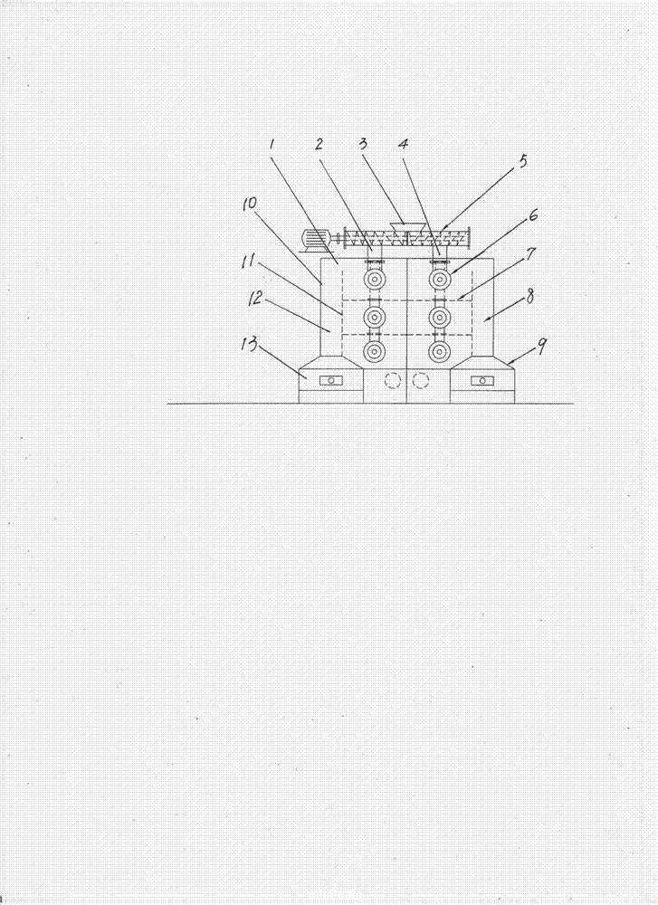
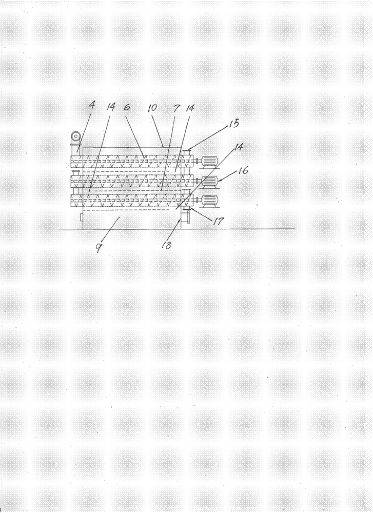
[0010] The invention is attached figure 1 , 2 As shown, the device comprises a single-screw bidirectional feeder 5, a cracking chamber 10, and two sets of helical crackers 6. The single-screw bidirectional feeder 5 is driven by a drive motor, and its feed port 3 is located in the middle of the feeder. , the spiral cracker 6 is driven by the driving motor 16, and each group of spiral crackers 6 is arranged vertically, and each cracker is connected by a connecting pipe. A group of spiral crackers, the positive and negative spirals of the single-screw bidirectional feeder 5 are fed to each group of spiral crackers 6 respectively; The two groups of spiral crackers 6 are provided with partitions 11 in the vertical direction respectively. The lower part of the partitions 11 is connected to the shells of the combustion furnaces 9 and 13, and forms a reflection hot air channel 8 with the inner wall of the cracking chamber 10, and a hot air channel is left on the upper part. 1; betwe...


PUM


Abstract

The invention relates to a reflective heated waste rubber and waste plastic thermal cracking device. The device comprises a feeder, a cracking chamber and two spiral cracking devices. The spiral cracking devices are vertically arranged. Two combustion furnaces are respectively arranged on both sides of the lower part of the cracking chamber. Separators are respectively arranged in a vertical direction outside the spiral cracking devices in the cracking chamber. The separators and inner walls on both sides of the cracking chamber form reflective hot air ducts, respectively. Hot air channels are reserved on the upper parts. Compared with conventional cracking devices, the reflective heated waste rubber and waste plastic thermal cracking device provided by the invention is high in degree of automation, large in production capacity and low in manufacturing cost which is half of that of conventional rotary furnaces, and the daily production capacity is twice as much as that of the conventional rotary furnaces. The spiral cracking device is prevented from being directly burned by flame, the upmost spiral cracking device is heated first to reach the higher temperature required by a feeding part. The reflective heated waste rubber and waste plastic thermal cracking device heats uniformly and has high thermal cracking efficiency. Retention time of hot air in the furnace is prolonged, so that the heat is adequately used, and the energy sources are saved. The reflective heated waste rubber and waste plastic thermal cracking device is in totally-enclosed continuous production and low in labor intensity, and no secondary pollution is generated.

Description

technical field [0001] The invention relates to a reflective heating waste rubber and waste plastic pyrolysis device, which is a double-reflection pyrolysis device Background technique [0002] Waste rubber and waste plastic thermal cracking renewable energy technology has made great progress in recent years [0003] Pyrolysis equipment also emerged as the times require, with a wide variety, but most of them are intermittently produced pyrolysis equipment, with low output, high labor intensity, and difficult operation, which restrict the development of this industry to varying degrees. Although the "continuous cracking device for waste plastics" (application number 201120077319.6) applied by the inventor in 2011 solved the problem of continuous production with continuous feeding, the combustion furnace of this design directly heats the bottom spiral cracker, which not only heats unevenly , and where high temperature is required at the top feed end, high temperature ...

Claims


Application Information

Patent Timeline
IPC IPC(8): C10G1/10C10G1/00C08J11/10
CPCY02W30/62
Inventor 李玉坤代先菊
Owner SHANGQIU SIHAI MACHINERY EQUIP MFG
Why Eureka
Try Eureka