
Urea ejector capable of forming vortex

A technology of injector and injector body, which is applied in the directions of machines/engines, chemical instruments and methods, mechanical equipment, etc., can solve the problems of complex structure, reduced atomization quality, poor spray atomization quality, etc., and achieves improved spray atomization. Quality, improved quality and efficiency, effect of improved atomization quality

Inactive Publication Date: 2012-12-19
CHONGQING FUEL INJECTION SYST CO LTD OF CHINA NAT HEAVY DUTY TRUCK GRP
View PDF6 Cites 2 Cited by
  • Summary
  • Abstract
  • Description
  • Claims
  • Application Information

AI Technical Summary

Problems solved by technology

[0003] The more commonly used automobile exhaust treatment devices generally use urea to treat the exhaust gas. The existing problems are: the spray atomization quality of the existing urea injector is poor, the utilization rate of the urea aqueous solution is low, and the treatment effect on the automobile exhaust gas is low. Difference
In addition, the sealing performance between the needle valve body and the injection hole body on the urea injector is poor. Moreover, during manufacture, in order to ensure the sealing effect, the assembly precision of the needle valve body and the injection hole body is required to be very high, resulting in low production efficiency
[0004] At present, in the fuel injection technology of vehicle engines, in order to improve the injection atomization quality of fuel, the structure for generating swirl is generally installed on the fuel injector, so that the fuel is sprayed in the form of swirl to improve combustion efficiency, but this The structure used to generate vortex in such devices cannot be directly used to solve the problem of poor atomization quality of urea injection, the reasons are:
[0005] On fuel injectors, in order to achieve the best fuel atomization effect, the structure used to generate swirl is generally set to be more complicated. The reason why such a complex structure can be applied depends on the high oil pressure during fuel injection. The oil pressure of fuel injection is generally 20Mpa, but the injection pressure of the urea injector used for exhaust gas treatment is relatively low, and its pressure generally does not exceed 0.9Mpa. If the complex structure used to generate swirl on the fuel injector is directly applied to urea injection In the device, not only will it not increase the injection effect of urea, but it will cause pressure loss during the urea injection process due to the complex structure, which will greatly reduce the pressure of the injected urea. This will not only fail to improve the atomization quality of urea injection, but will It will reduce the quality of atomization, reduce the utilization rate of urea aqueous solution, and the treatment effect on automobile exhaust is also worse
Due to the relatively mature design and structure of other existing vehicle-mounted devices, the injection pressure of urea solution cannot be increased rashly, and there is no positive correlation between the injection pressure of urea solution and the effect of exhaust gas treatment.

Method used


Image

  • Urea ejector capable of forming vortex
  • Urea ejector capable of forming vortex
  • Urea ejector capable of forming vortex

Examples


Embodiment Construction

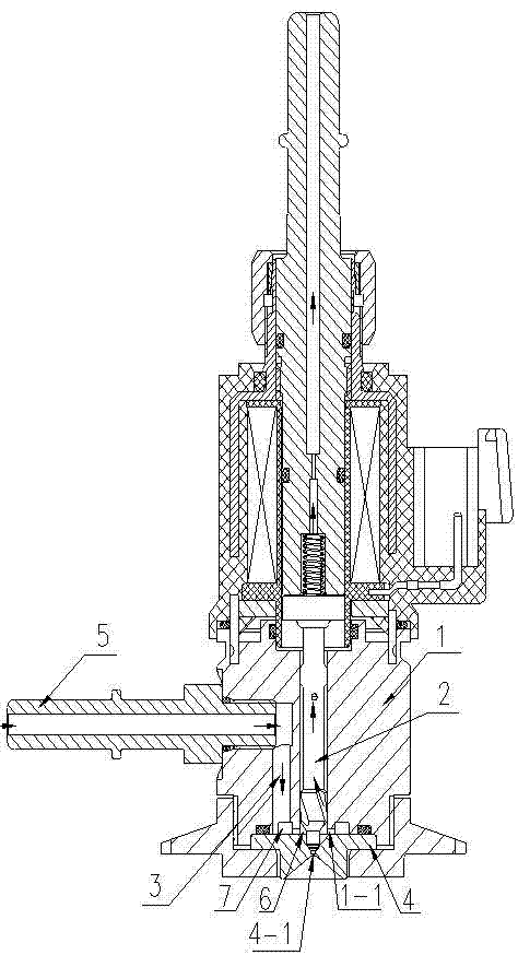
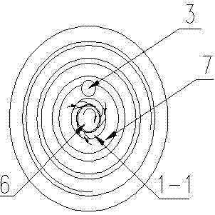
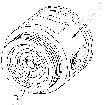
[0021] The structure of the present invention is: including: injector body 1, needle valve body 2, urea liquid inlet channel 3, injection hole body 4 and urea liquid inlet pipe joint 5, and the improvement is that the injection hole body 4 is arranged on the injector body 1 In the lower part, the lower end of the injector body 1 is provided with an annular protrusion 1-1; the lower end surface of the annular protrusion 1-1 is in contact with the upper end surface of the injection hole body 4, and the annular protrusion 1-1 connects the injection hole body 4 and the injector body 1. The connection is divided into two chambers, the chamber inside the annular protrusion 1-1 forms the injection chamber 6, the chamber outside the annular protrusion 1-1 forms the liquid inlet chamber 7, and the annular protrusion 1-1 is provided with multiple arc-shaped holes, the arc-shaped holes run through the annular protrusion 1-1, and the bending directions of the plurality of arc-shaped holes ...


PUM


Abstract

The invention relates to a urea ejector capable of forming a vortex. The urea ejector comprises an ejector body, a needle valve body, a urea solution inlet passage, an ejection hole body and a urea solution inlet pipe joint. The improvement of the invention is as follows: a structural body capable of forming the vortex is arranged between the ejection hole body and the ejector body to ensure that the urea solution is ejected in the form of the vortex. The urea ejector disclosed by the invention has the beneficial technical effects that under the condition that other peripheral devices are not changed, the ejection atomization quality of the urea water solution is improved; the treatment effect of vehicle exhaust is improved; the structure is simple; and the application range is wide.

Description

technical field [0001] The invention relates to an automobile tail gas treatment device, in particular to a urea injector capable of forming a vortex. Background technique [0002] Automobile exhaust is one of the main causes of environmental pollution. Therefore, how to reduce the environmental pollution caused by automobile exhaust is a common problem faced by mankind. [0003] The more commonly used automobile exhaust treatment devices generally use urea to treat the exhaust gas. The existing problems are: the spray atomization quality of the existing urea injector is poor, the utilization rate of the urea aqueous solution is low, and the treatment effect on the automobile exhaust gas is low. Difference. In addition, the sealing performance between the needle valve body and the injection hole body on the urea injector is poor. Moreover, during manufacture, in order to ensure the sealing effect, the assembly precision of the needle valve body and the injection hole bod...

Claims


Application Information

Patent Timeline
Patent Type & Authority Applications(China)
IPC IPC(8): F01N3/20B01D53/94
CPCY02T10/24Y02A50/20Y02T10/12
Inventor 邱龙彬熊长国卓兴军
Owner CHONGQING FUEL INJECTION SYST CO LTD OF CHINA NAT HEAVY DUTY TRUCK GRP
Learn More