
A fuel tank oil-gas separation structure assembly

A technology of separation structure and oil and gas separation chamber, which is applied to gasoline barrels, liquid fuel feeders, adding non-fuel substances to fuel, etc., can solve problems such as inability to separate oil and gas, insufficient space volume, and increase manufacturing costs, and achieve a simple structure. Reasonable and compact, avoid solder joint loosening, reliable effect of oil and gas separation

Active Publication Date: 2015-12-09
常州豪爵铃木摩托车有限公司
View PDF6 Cites 0 Cited by
  • Summary
  • Abstract
  • Description
  • Claims
  • Application Information

AI Technical Summary

Problems solved by technology

[0003] Among the existing oil-gas separation devices, some are assembled on the outside of the fuel tank, because the exposure of the device will affect the appearance of the whole vehicle, so it can only be used on some specific models; some are integrated in the fuel tank cap, Due to the limitation of the structure of the fuel tank cap, the space for oil and gas separation is insufficient, and the oil and gas cannot be separated effectively; appearance quality; some are arranged in the position where fuel is easy to intrude, which reduces the separation effect of the separation device; some use rubber and filter elements, which reduces the reliability of the separation device; some use more complicated pipelines and more brackets , which increases the difficulty of manufacture; some apply complex labyrinth structure, which increases the manufacturing cost; and some large-scale devices are not suitable for promotion and use on compact motorcycles

Method used


Image

  • A fuel tank oil-gas separation structure assembly
  • A fuel tank oil-gas separation structure assembly
  • A fuel tank oil-gas separation structure assembly

Examples


Embodiment Construction

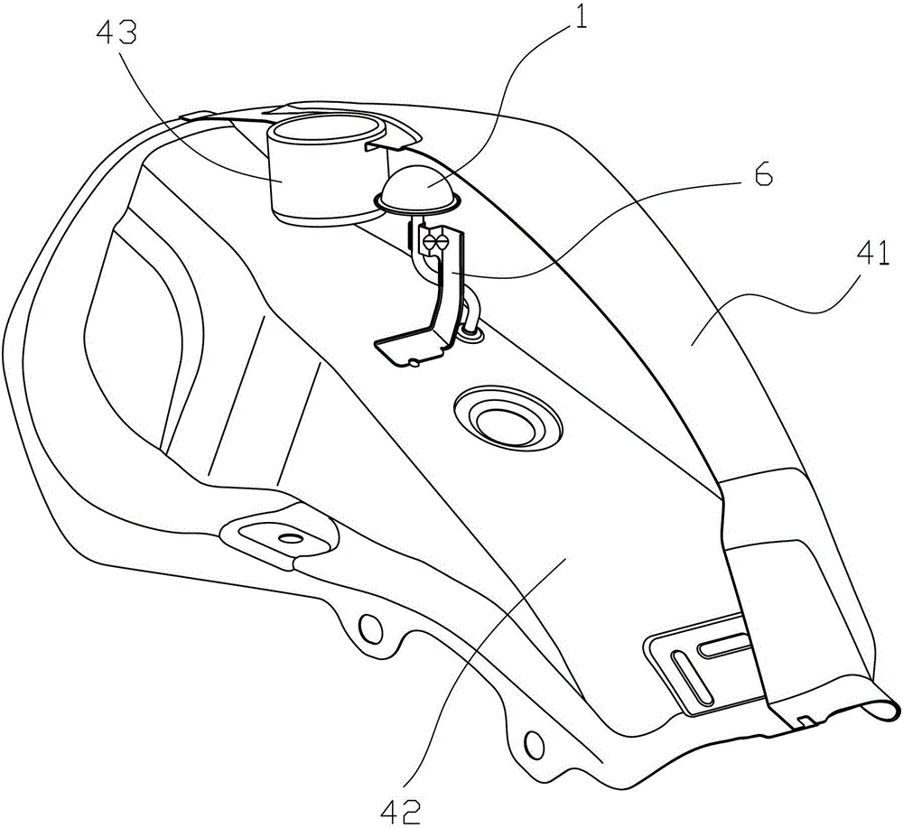
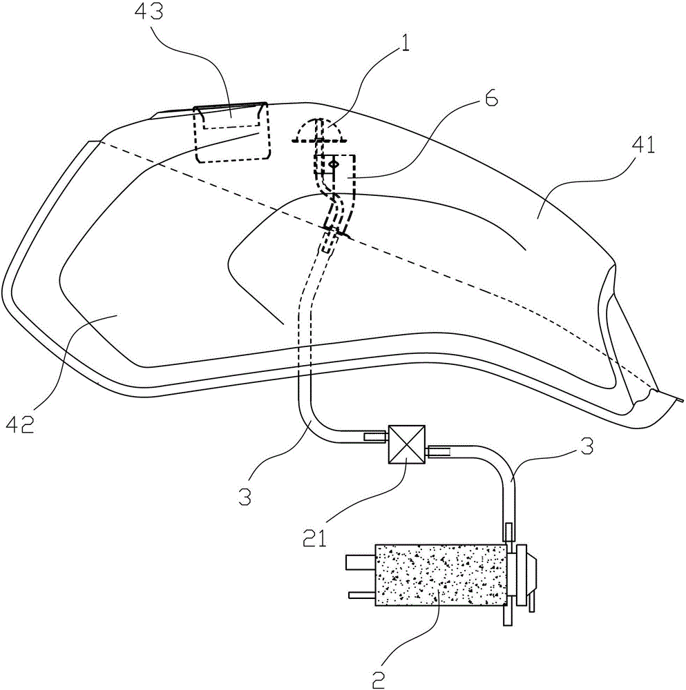
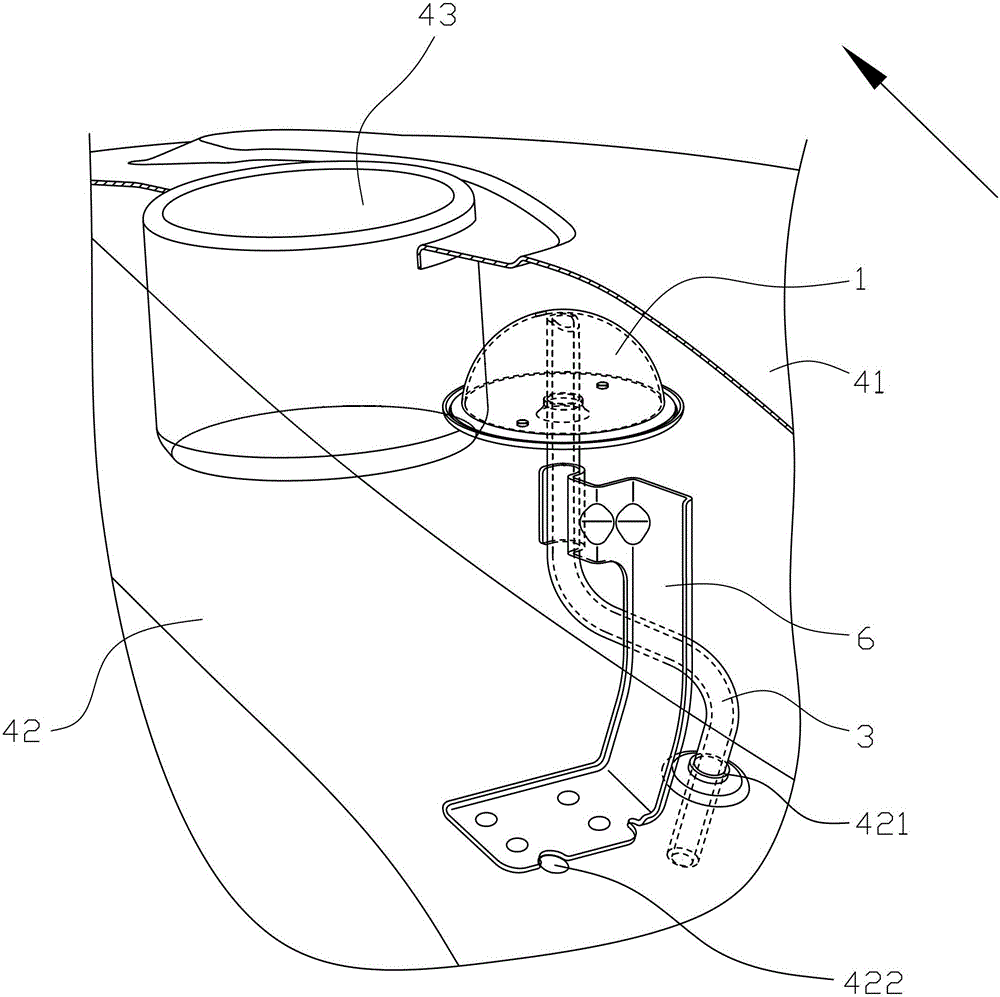
[0031] refer to Figure 1~Figure 9 , a fuel tank oil-gas separation structure assembly of the present invention, which includes a fuel tank and an oil-gas separation device arranged in the fuel tank, the oil-gas separation device includes an oil-gas separation chamber 1 and a vent pipe connecting the oil-gas separation chamber 1 and the carbon tank 2 3. The oil-gas separation chamber 1 is composed of an upper part 11 and a lower part 12. The fuel tank is divided into an upper casing 41 and a lower casing 42. One end of the breather pipe 3 passes through the perforation 121 provided on the lower part 12 of the oil-gas separation chamber. After that, it communicates with the oil-gas separation chamber 1, and the other end of the vent pipe 3 passes through the through hole 421 provided on the lower casing 42 to communicate with the carbon canister 2, preferably after the vent pipe 3 passes through the lower casing 42, it can be connected with a dump stop valve 21 to prevent the l...


PUM


Abstract

The invention discloses an oil-gas separating structure assembly for a fuel oil tank, which comprises the fuel oil tank and an oil-gas separating device arranged in the fuel oil tank, wherein the oil-gas separating device comprises an oil-gas separating chamber and a ventilating pipe; the ventilating pipe is used for communicating the oil-gas separating chamber with a coal tank; a cavity of the oil-gas separating chamber is composed of an upper part and a lower part; a fuel oil steam guiding inlet and a liquid fuel oil guiding outlet are respectively arranged on the upper part and the lower part of the oil-gas separating chamber; a refueling conduit is arranged under a refueling port of the fuel oil tank; the oil-gas separating device is located in a position behind the refueling conduit; a lower edge of the oil-gas separating chamber is higher than the lower edge of the refueling conduit; and the fuel oil steam guiding inlet on the oil-gas separating chamber is faced to the refueling conduit. By using the oil-gas separating structure assembly for the fuel oil tank, the probability of the liquid oil to invade into the oil-gas separating chamber and the ventilating pipe is effectively reduced, the liquid fuel oil invading into the oil-gas separating device can smoothly flow back to the fuel oil tank, and meanwhile, the fuel oil steam can be normally introduced into the ventilating pipe, and the separation of the liquid fuel oil and the fuel oil steam is reliably realized.

Description

technical field [0001] The invention relates to a fuel tank oil-gas separation structure assembly, in particular to a fuel tank oil-gas separation structure assembly applied to motorcycles. Background technique [0002] At present, the motorcycles on the market that correspond to the national standard GB20998 for the control of motorcycle fuel evaporative pollutant emissions generally use an oil-gas separation device to separate the fuel in the fuel tank into liquid fuel and fuel vapor. The fuel vapor is introduced into the carbon canister through the pipeline, which is first adsorbed by the canister and then desorbed into the engine to participate in combustion, so as to meet the requirements of the emission control of fuel evaporation pollutants. [0003] Among the existing oil-gas separation devices, some are assembled on the outside of the fuel tank, because the exposure of the device will affect the appearance of the whole vehicle, so it can only be used on some specifi...

Claims


Application Information

Patent Timeline
Patent Type & Authority Patents(China)
IPC IPC(8): F02M37/00F02M25/08B62J35/00
Inventor 王彦军邹志民李伟雷庆荣
Owner 常州豪爵铃木摩托车有限公司
Learn More