LED (light-emitting diode) light distribution system adopting free-form surface lens and reflector as well as design method of LED light distribution system

A technology of curved lens and system design, applied in the field of LED light distribution system, can solve problems such as inability to maintain, the direction of light cannot be adjusted, and high optical efficiency

Active Publication Date: 2012-12-19
刘木清
View PDF3 Cites 7 Cited by
  • Summary
  • Abstract
  • Description
  • Claims
  • Application Information

AI Technical Summary

Problems solved by technology

[0004] 1. All LEDs are placed in the sealed cavity formed by the aluminum lamp housing and the transparent waterproof outer cover, and the sealing is realized by waterproof glue. In this way, after any LED fails, maintenance will be extremely difficult, especially if it cannot be repaired on site.
[0005] 2. The optical loss of the lens or reflector used for light distribution is at least 10%, and the waterproof transparent cover also has an optical loss of more than 10%.
However, this method can only adjust the direction of the light emitted by the LED within a certain angle (usually 60 degrees) to its optical axis, and cannot adjust the direction of the light greater than this angle.
Therefore, high optical efficiency cannot be obtained

Method used


Image

  • LED (light-emitting diode) light distribution system adopting free-form surface lens and reflector as well as design method of LED light distribution system
  • LED (light-emitting diode) light distribution system adopting free-form surface lens and reflector as well as design method of LED light distribution system
  • LED (light-emitting diode) light distribution system adopting free-form surface lens and reflector as well as design method of LED light distribution system

Examples


Embodiment 1

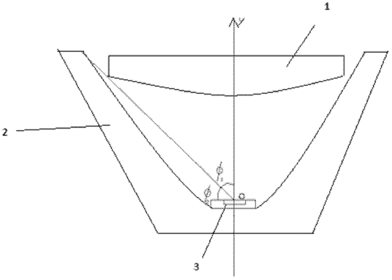
[0098] Embodiment 1: the optical system of lens and reflector is taken as attached figure 2 In the form shown, part of the light from the light source is refracted to the target surface through the lens, and the other part is reflected to the target surface through the reflector without being refracted by the lens. The inner surface of the lens adopts a free-form surface, and the outer surface adopts a plane. The light source adopts Lambertian LED, namely I is the central light intensity. The target surface is 10 meters away from the light source, and it is required to form a giant uniform spot with a length of 30 meters and a width of 10 meters, and its center is on the y-axis.

[0099] First, divide the light emitted by the LED, take φ0=60 degrees, then the light emitted by the LED in the range of 0°≤φ0 ≤φ≤90° adopt reflector design.

[0100] Place the LED at the origin of the coordinate system so that its central axis coincides with the y-axis. A known And the illumi...

Embodiment 2

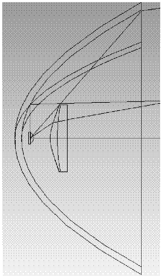
[0122] Embodiment 2: the optical system of lens and reflector is taken as attached Figure 4 In the form shown, part of the light from the light source is refracted to the target surface through the lens, and the other part is reflected to the lens part through the reflector, and then refracted to the target surface. The inner surface of the lens adopts a free-form surface, and the outer surface adopts a plane. The calculation of this form of optical system is relatively complicated for reflectors, because the light is reflected first, then refracted, and finally incident on the target surface, which needs to be combined with the reflectance formula and the refractive index formula. The mapping relationship for light is the same as in Embodiment 1, but the obtained expression needs to be substituted into the reflectance formula and the refractive index formula. After listing the equations, the points on the surface are obtained through computer iterative solution, and then th...

Embodiment 3

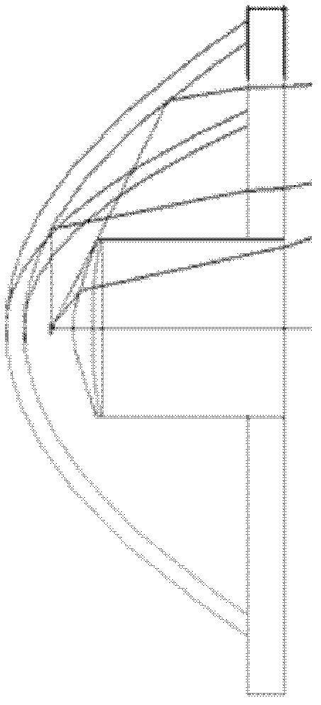
[0123] Embodiment 3: the optical system of lens and reflector is taken as attached Figure 5 The form shown adopts the integrated design of lens and reflector. Part of the light from the light source is refracted to the target surface through the lens, and the other part is totally reflected to the target surface through the inner surface of the reflector. The inner surface of the lens adopts a free-form surface, and the outer surface adopts a plane. This form of reflector part needs to consider that the light incident on the reflective surface needs to be refracted once to enter the medium. refraction formula [ 1 + n 2 - 2 n ( Out → · In → ) ...


PUM


Abstract

The invention relates to an LED (light-emitting diode) light distribution system adopting a free-form surface lens and reflector as well as a design method of the LED light distribution system. With the adoption of the method, the LED light distribution system and an LED-packaged primary optical system are obtained. According to the design method of the LED light distribution system, light emitting from an LED is divided into two parts, the two parts of light are divided according to an included angle Phi between light rays and an optical axis of the LED, specifically, when Phi is greater than or equal to 0 degree and less than phi 0, the rays are refracted through the free-form surface lens and then exit, and when Phi is greater than or equal to the phi 0 and is less than or equal to 90 degrees, and the rays are reflected through the reflector and exit, or are reflected by the reflector and then exit through a common lens or the free-form surface lens. With the adoption of the LED light distribution system and the design method, a lens model and a reflector model can be rapidly generated according to requirements, and the only needed thing is to change known conditions; the defect that light energy within a 2Phi solid angle can not be completely utilized if only the reflector is utilized is overcome, and the energy utilization ratio is high; and the difficulty in light distribution generated due to limitation of refraction angle since only the lens is adopted is overcome, and theoretically, light distribution realizing transformation at any angle on light rays at any angle can be achieved.

Description

technical field [0001] The invention belongs to the technical field of non-imaging optics and illumination, and in particular relates to an LED light distribution system using a free-form surface lens and a reflector and a design method thereof. Background technique [0002] It is a classic problem in the lighting industry that a point light source (such as LED) passes through a lens and a reflector to form a specific spot that meets the lighting needs. In recent decades, the gradual development of non-imaging optics has begun to solve this problem. Scientists such as H.Ries have studied Tailoring (cutting method). Domestic researchers also have related patents and papers explaining how to design free-form lenses. However, there is no relevant research on how to effectively design light distribution for LEDs from all angles. reports. However, only using lenses or reflectors cannot optimize the light distribution of the light energy of LEDs, resulting in low efficiency. Th...

Claims


Application Information

Patent Timeline
Patent Type & Authority Applications(China)
IPC IPC(8): F21V13/04F21Y101/02
Inventor 刘木清陶鑫
Owner 刘木清
Why Eureka
Try Eureka