[0046] Describe the present invention below in conjunction with specific embodiment:
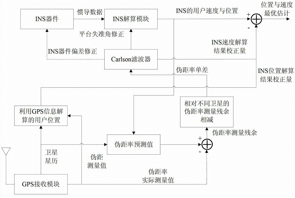
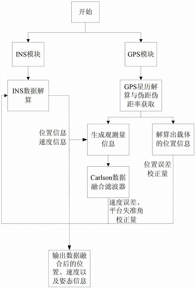
[0047] The specific implementation diagram of the data fusion method of the present embodiment is as follows figure 1 As shown in the figure, the user uses the collected raw data of the INS device to calculate the data of INS navigation, calculates the attitude information, position information and speed information of the carrier, counts the INS calculation module, and performs a combined navigation every 5 times. Data Fusion. Using the reduced-dimensional data fusion method based on Carlson filtering, the data fusion of the GPS navigation system and the INS navigation system is realized. The specific steps are as follows:
[0048] Step 1: Use the satellite position information and pseudorange information obtained by the GPS receiver, and use the above information to calculate the current user's position (x y z) and the user's speed (v ) through the least squares method. x v y v z ); pass this value to the INS module to update the location information of the INS module;
[0049] Step 2: Use the ephemeris information obtained by the GPS receiver to calculate the position information and speed information of the required satellites, wherein the position information of the ith satellite is (x i y i z i ), the speed information is x . i y . i z . i ; by formula
[0050] δ ρ . ij = δ ρ . i - δ ρ . j
[0051] = ( e 1 i - e 1 j ) δ v x + ( e 2 i - e 2 j ) δ v y + ( e 3 i - e 3 j ) δ v z + ϵ ρ . ij
[0052] . . .
[0053] δ ρ . mj = δ ρ . m - δ ρ . j
[0054] = ( e 1 m - e 1 j ) δ v x + ( e 2 m - e 2 j ) δ v y + ( e 3 m - e 3 j ) δ v z + ϵ ρ . mj
[0055] Get the observation set of the data fusion system Z = δ ρ . ij · · · δ ρ . mj , where δv x , δv y , δy z is the velocity error information, i, j, m are the corresponding satellite serial numbers, It is the projection of the direction vector of the i-th satellite from the GPS receiver on the geodetic coordinate system:
[0056] e 1 i = x - x i [ ( x - x i ) 2 + ( y - y i ) 2 + ( z - z i ) 2 ]
[0057] e 2 i = y - y i [ ( x - x i ) 2 + ( y - y i ) 2 + ( z - z i ) 2 ]
[0058] e 3 i = z - z i [ ( x - x i ) 2 + ( y - y i ) 2 + ( z - z i ) 2 ] ,
[0059] is the residual information of the pseudorange rate of the GPS receiver relative to the i-th satellite: is the predicted value of the pseudorange rate of the i-th satellite relative to the GPS receiver:
[0060] ρ . c i = e 1 i · ( v x - x . i ) + e 2 i · ( v y - y . i ) + e 3 i · ( v z - z . i ) ,
[0061] is the measured value of the pseudorange rate of the i-th satellite relative to the GPS receiver, is the measurement error of the pseudorange rate between the i-th satellite and the j-th satellite;
[0062] Step 3: Establish the measurement equation Z=HX+V of the data fusion system, X is the state vector of the data fusion system, H is the measurement matrix, V is the measurement noise, where
[0063] X=[δv x δv y δv z δε x δε y δε z d x d y d z b x b y b z ],
[0064] δε x , δε y , δε z is the platform misalignment angle information, d x , d y , d z is the gyroscope bias information, b x , b y , b z is the zero bias information of the accelerometer; the measurement matrix of the system is U×12, where U is the number of observed satellites. The original observation matrix is 2U×15, which reduces the amount of data by 60% compared to the original observation matrix.
[0065] The measurement matrix of the data fusion system is obtained from the measurement equation Z=HX+V:
[0066] H = e 1 i - e 1 j , e 2 i - e 2 j , e 3 i - e 3 j , 0 1 × 3 , 0 1 × 3 , 0 1 × 3 . . . e 1 m - e 1 s , e 2 m - e 2 s , e 3 m - e 3 s , 0 1 × 3 , 0 1 × 3 , 0 1 × 3
[0067] Where s is also the satellite serial number;
[0068] Step 4: Perform Carlson filtering on the observation Z of the data fusion system. The specific filtering steps are:
[0069] Step 4.1: Initialize the Carlson filter;
[0070] Step 4.2: Perform Carlson filtering on the observation set Z of the data fusion system, wherein the k-th filtering process includes the time update process of Carlson filtering and the measurement update process of Carlson filtering:
[0071] Step 4.2.1: For the time update process of the kth Carlson filter, record the iteration result matrix E as
[0072] E = U k - 1 T Φ k , k - 1 T Γ k - 1 Q k - 1 1 / 2 l × n n × n
[0073] where l is the dimension of the driving noise of the data fusion system, n is the dimension of the state vector of the data fusion system, U k-1 is the upper triangular decomposition matrix of the covariance matrix of the k-1th filtering, Φ k,k-1 is the discretized form of the state matrix of the data fusion system, Q k-1 is the state noise, Γ k-1 is the state noise driving matrix, Φ k,k-1 =I+F t, where t is the sampling time; F is the state matrix of the data fusion system, which is defined by the state equation of the data fusion system:
[0074] X . i ( t ) = δ v . 3 × 1 δ ϵ . 3 × 1 d . 3 × 1 b . 3 × 1 = F · X = - F i δ ϵ 3 × 1 i + C b i b 3 × 1 C b i d 3 × 1 - A d 3 × 1 - A b 3 × 1
[0075] get, where F i is the comparison matrix, is the direction cosine matrix from the carrier coordinate system to the geodetic coordinate system, A is the first-order Markov process coefficient matrix; here, the data is written using the acceleration information obtained by the INS device and the direction cosine matrix information column obtained by the INS solution module The state matrix F of the fusion system 12×12 differential form. Compared with the original system, the state matrix of the system is reduced from 15 dimensions to 12 dimensions, the amount of data is reduced from 225 to 144, and the data processing time is also reduced accordingly.
[0076] For formula:
[0077] U k / k - 1 ( g , g ) = E ( g ) T E ( g ) V g = 1 U k / k - 1 ( g , g ) E ( g ) U k / k - 1 ( b , g ) = E ( b ) T V g , b = 1,2 , · · · , g - 1 E ( b ) = E ( b - 1 ) - U k / k - 1 ( b , g ) V g , b = 1,2 , · · · , g - 1
[0078] Iterates in the order of g=n,n-1,n-2,...,2,1, and after n recursion, the upper triangular matrix decomposition matrix U of the covariance prediction matrix of the kth filtering is obtained k/k-1 , where U k/k-1 (g, g) is U k/k-1 The element value of row g in column g, E (g) is the gth column of E;
[0079] Step 4.2.2: For the measurement update process of the k-th Carlson filter, the sequential processing method is adopted: For each observation in the observation set Z of the data fusion system, the following steps are used:
[0080] The processing process for the rth observation is: for the formula Perform an iterative operation, q from 1 to n, where d q =d q-1 +a(q), is the noise co-defense of the rth observation, a = U k / k - 1 T ( H k r ) T = a ( 1 ) a ( 2 ) · · · a ( n ) T , is the rth row of the measurement matrix of the data fusion system, e 0 =0, where and respectively represent U k The qth column and U of k/k-1 The qth column of ; get the upper triangular decomposition matrix of the kth filtering covariance matrix U k = U k ( 1 ) U k ( 2 ) · · · U k ( n ) , will U k Stored to participate in the next time update process of Carlson filtering, U should be changed before the end of sequential processing k As the next covariance estimation matrix;
[0081] The state estimate for the sequential processing of the rth observation is in is the state vector value of the k-1th filtering, is the value of the rth observation obtained by the kth filtering, X ^ k / k - 1 = Φ k / k - 1 X ^ k - 1 ;
[0082] Continue to use the observations to estimate the state, and finally obtain the state estimate of the last observation m in the observation set Z of the data fusion system as is the final state estimate;
[0083]Step 5: Use the result obtained in Step 4 Correct the INS calculation module: use the speed information solved by the INS to subtract the speed error obtained by the Carlson filter to obtain the corrected speed information; use the formula
[0084] C ^ E b = 1 ϵ z - ϵ y - ϵ z 1 ϵ x ϵ y - ϵ x 1 · C E b
[0085] get the corrected direction cosine matrix For the direction cosine matrix from the geodetic coordinate system obtained by the INS module to the carrier coordinate system, the acceleration obtained by the INS device and the calculated accelerometer bias information b x , b y , b z Subtract the corrected acceleration, and combine the angular velocity obtained by the INS device with the calculated gyroscope bias information d x , d y , d z Subtract the corrected angular velocity information.