Color filter and forming method thereof

A color filter and color-resist layer technology, which is applied in the direction of optical filters, optics, and optomechanical equipment, can solve problems affecting the orderly arrangement of liquid crystals and light leakage at the edge of pixels, so as to achieve easy alignment and prevent light leakage at the edge of pixels , forming the effect of simple process

Inactive Publication Date: 2012-12-19
SHANGHAI TIANMA MICRO ELECTRONICS CO LTD
View PDF4 Cites 15 Cited by
  • Summary
  • Abstract
  • Description
  • Claims
  • Application Information

AI Technical Summary

Problems solved by technology

Due to the existence of horns 107, the orderly arrangement of liquid crystals will be affected, so light leakage at the edge of pixels is more likely to occur in the display device

Method used


Image

  • Color filter and forming method thereof
  • Color filter and forming method thereof
  • Color filter and forming method thereof

Examples


no. 1 example

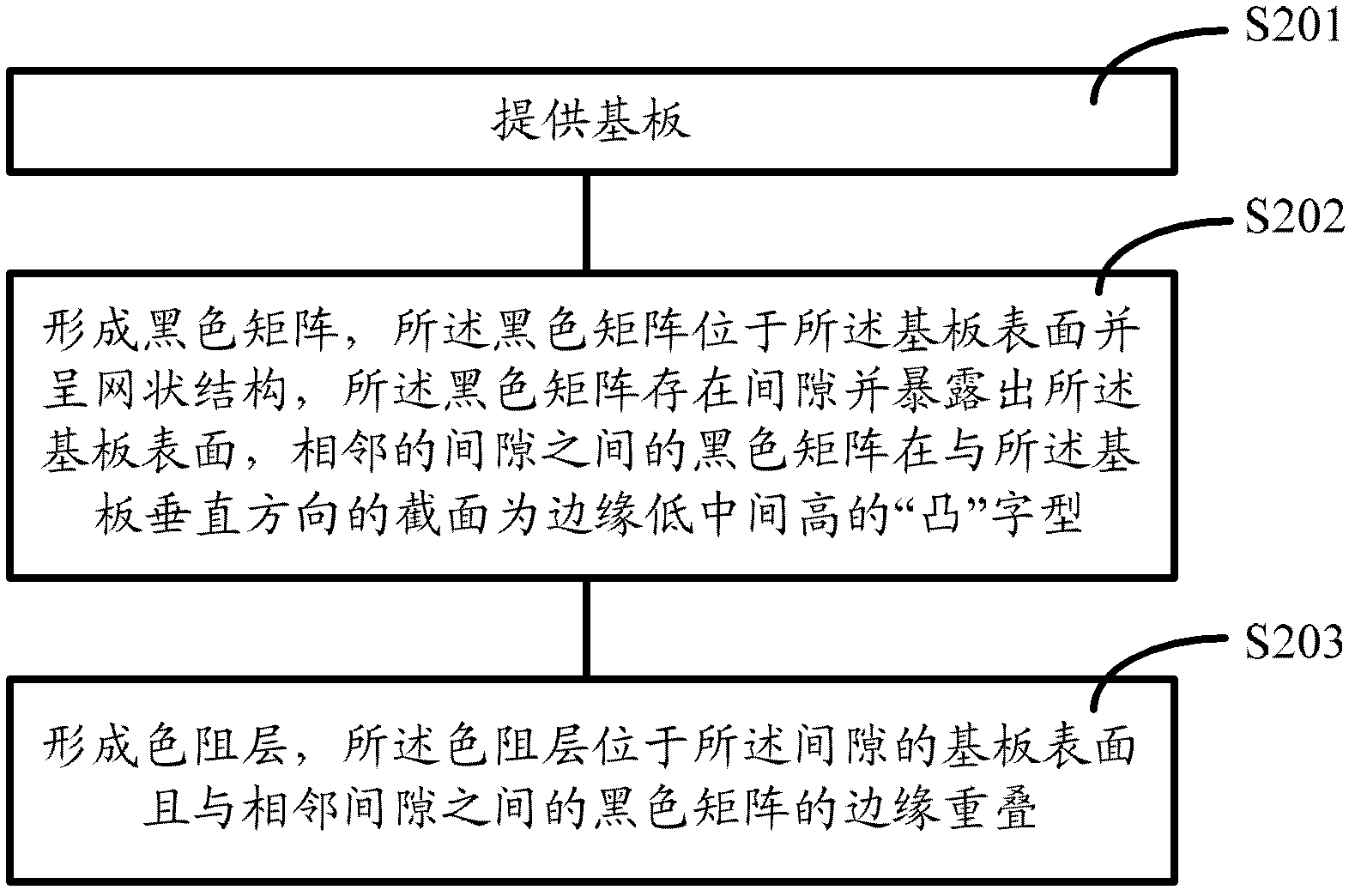
[0041] Please refer to figure 2 , the inventor of the embodiment of the present invention provides a method for forming a color filter, including:

[0042] Step S201, providing a substrate;

[0043] Step S202, forming a black matrix, the black matrix is ​​located on the surface of the substrate and has a network structure, the black matrix has gaps and exposes the surface of the substrate, and the black matrix between adjacent gaps is perpendicular to the substrate The cross-section of the direction is a "convex" shape with low edges and high middle;

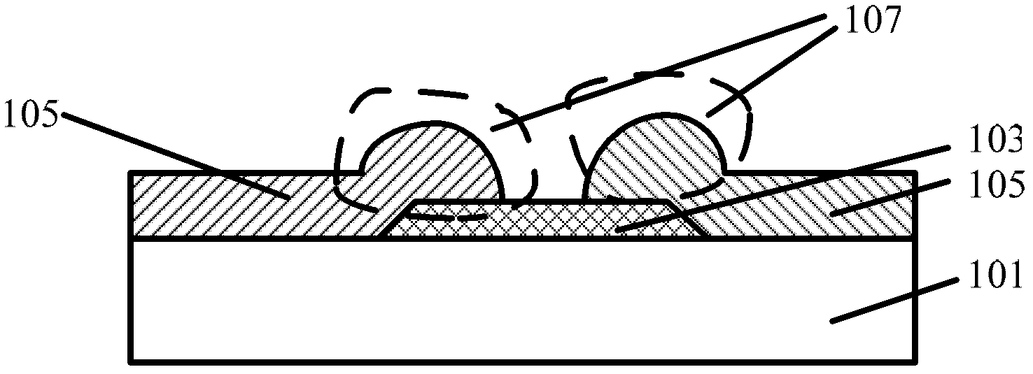
[0044] Step S203 , forming a color-resist layer, the color-resist layer is located on the substrate surface of the gap and overlaps with the edge of the black matrix between adjacent gaps.

[0045] In this embodiment, specific reference can be made to Figure 3 ~ Figure 6 Schematic diagram of the cross-sectional structure of the method for forming the color filter.

[0046] Execute step S201, please refer to image 3 , pro...

no. 2 example

[0070] Please refer to Figure 8 , the inventors of the embodiments of the present invention also provide a method for forming a color filter, including:

[0071] Step S401, providing a substrate, a black matrix with a network structure is formed on the surface of the substrate, the black matrix has gaps and exposes the surface of the substrate;

[0072] Step S402, forming a color-resist layer, the color-resist layer is located on the surface of the substrate and at the edge of the black matrix between adjacent gaps, and the thickness of the color-resist layer at the edge of the black matrix between adjacent gaps is less than The thickness of the color resist layer on the surface of the substrate.

[0073] In this embodiment, specific reference can be made to Figure 9 ~ Figure 10 Schematic diagram of the cross-sectional structure of the method for forming the color filter.

[0074] Execute step S401, please refer to Figure 5 with Figure 9 A substrate 501 is provided, a...


PUM

PropertyMeasurementUnit
thicknessaaaaaaaaaa

Abstract

The invention provides a color filter which comprises a base plate, black matrixes and color resistance layers, wherein the black matrixes are arranged on the surface of the base plate and are in lattice structures, the black matrixes are at intervals and are exposed out of the surface of the base plate, and the sections of the black matrixes between adjacent intervals vertical to the base plate is in the shape of a Chinese character TU (convex) with a low edge and a high central part; and the color resistance layers are arranged on the surfaces of the base plate at the intervals and are superposed with the edges of the black matrixes between the adjacent intervals. The invention further provides a forming method of the color filter. According to the forming method of the color filter, a black matrix is formed by utilizing a half-gray mask plate so that an ox horn can be reduced, even eliminated, and the light leakage of pixel edge of a display device is prevented; and the forming process is simple and the contrast ratio of the display is high.

Description

technical field [0001] The invention relates to the field of liquid crystal display, in particular to a color filter and a forming method thereof. Background technique [0002] A liquid crystal display (LCD) has advantages that traditional cathode ray tube displays cannot achieve, such as low-voltage operation, no radiation scattering, light weight, and small size. Therefore, liquid crystal display has become the main subject of display research this year, and it is developing toward colorization. [0003] Most of the currently colored liquid crystal displays use a combination of a backlight (Black Light, BL) and a color filter (color filter) to achieve the effect of colorization. The structure of the color filter is usually as follows figure 1 shown. [0004] figure 1 It is a schematic cross-sectional structure diagram of a color filter in the prior art. Please refer to figure 1 A black matrix 103 is arranged on the surface of the glass substrate 101, and red (R), gre...

Claims


Application Information

Patent Timeline
Patent Type & Authority Applications(China)
IPC IPC(8): G02B5/20G02F1/1335G03F7/00
Inventor 温福正刘倩
Owner SHANGHAI TIANMA MICRO ELECTRONICS CO LTD
Why Eureka
Try Eureka