
Electric transmission system and control method thereof

A technology of electric transmission and main control board, which is applied in the field of electric transmission, can solve the problems of complex interlacing of signal cables, difficult maintenance, inconvenient wiring, etc., and achieve the effect of eliminating hidden dangers of signal interference, satisfying high-power transmission, and simple expansion

Active Publication Date: 2012-12-19
SHENZHEN INVT ELECTRIC
View PDF9 Cites 1 Cited by
  • Summary
  • Abstract
  • Description
  • Claims
  • Application Information

AI Technical Summary

Problems solved by technology

For example, in high-power transmission applications, the positions of the power units are usually relatively far away from each other, which causes great inconvenience to the wiring of various signal detections on the adapter board, and the intertwining of signal cables is complicated, which is not only difficult to maintain, but also easy to cause unknown interference
Furthermore, the application requirements of high-power transmission are always changing. For larger power expansion or more complex applications, due to the limitation of the adapter board hardware and the relatively simple control of the control board, it cannot be flexible, which is not conducive to the product's market presence. Large-scale promotion and application

Method used


Image

  • Electric transmission system and control method thereof
  • Electric transmission system and control method thereof
  • Electric transmission system and control method thereof

Examples


Embodiment 1

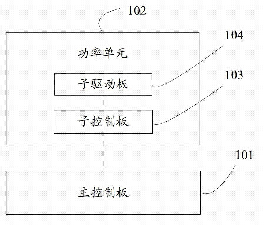
[0031] like figure 1 As shown, the embodiment of the present invention provides an electric drive system, including a main control board 101 and a power unit 102, and the power unit 102 includes a sub-control board 103 and a sub-drive board 104 connected to the sub-control board 103, The sub-control board 103 is connected to the main control board 101 , and the main control board 101 is used to control the sub-control board 103 .

[0032] The main control board 101 can send a control signal to the sub-control board 103 by receiving the detection data information of the power unit 102 transmitted by the sub-control board 103, so as to realize the control of the sub-control board 102. Board 103 controls. The sub-control board 103 can receive the control signal of the main control board 101, and generate a drive signal, and transmit the drive signal to the sub-drive board 104, and the sub-drive board 104 outputs specific operation signals, such as fan output signal, buffer pull-...

Embodiment 2

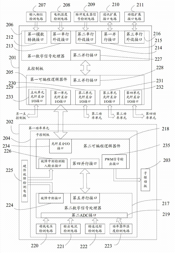
[0034] like figure 2As shown, the embodiment of the present invention provides another electric drive system, including a main control board 201 and a first power unit 202 . The first power unit 202 includes a sub-control board 204 and a sub-drive board 203 connected to the sub-control board 204, the sub-control board 204 is connected to the main control board 201, and the main control board 201 is used to control The sub-control board 204 .

[0035] The main control board 201 includes a first digital signal processor 206 and a first programmable logic device 205, the first digital signal processor 206 is connected to the first programmable logic device 205, and the first programmable The logic device 205 is connected to the sub-control board 204 .

[0036] The first digital signal processor 206 is provided with a first analog-to-digital conversion (ADC, Analog-to-Digtal Converter) interface 212, a first serial peripheral device (SPI, Serial Peripheral Interface) interface ...

Embodiment 3

[0048] A control method for an electric transmission system in this embodiment is applied to the electric transmission system described in Embodiment 1 or 2.

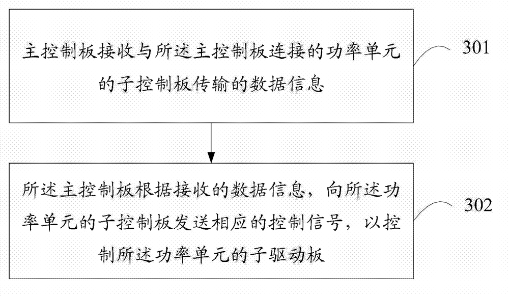
[0049] Such as image 3 As shown, a control method for an electric drive system, comprising:

[0050] 301. The main control board receives data information transmitted by a sub-control board of a power unit connected to the main control board.

[0051] In this embodiment, the sub-control board collects the detection data through each detection circuit connected to the sub-control board. The detection data may include: output current, bus voltage, overcurrent, fault, speed tracking and other detection data. The data information may be detection data. When the main control board is connected to several power units, step 301 specifically further includes: the main control board receiving data information transmitted by the sub-control boards of the several power units connected to the main control board.

[0052] 302. ...


PUM


Abstract

The invention discloses an electric transmission system. The electric transmission system comprises a master control board and a power unit, wherein the unit power comprises a sub control board and a sub control driving board which is connected with the sub control board, the sub control board is connected with the master control board, and the master control board is used for controlling the sub control board. The invention also provides a corresponding control method, an electric transmission capacity expansion system and a control method of the electric transmission capacity expansion system. According to the electric transmission system and the control method, disclosed by the invention, the system structure in master control and unit sub control is adopted, the collection of a bus voltage signal, an input / output phase signal and the like is finished by the power unit, the unused placing of a functional circuit module is avoided, and the problems such as intricate circuit, difficult maintenance, inconvenient wiring and interference hidden danger brought by collecting an over-current detection signal and the like by an adapter board in the prior art are overcome; and in addition, the flexibility of the system configuration is enhanced, the parallel operation and the capacity expansion in larger power are easy, and the requirement on large-power transmission can be met.

Description

technical field [0001] The invention relates to the field of electric transmission, in particular to an electric transmission system and a control method thereof. Background technique [0002] As we all know, the frequency converter is an independent electrical transmission system with a single machine. In general, a single machine frequency converter can only meet the application requirements of a single drive with a small and medium power level, but for the application requirements of a single drive or multiple drives with a high power level, A stand-alone frequency converter is not enough, and it often requires a combination of multiple stand-alone frequency converters to work together. For example, in order to realize a high-power single-drive system application, multiple frequency converter power units of appropriate power levels need to be paralleled and expanded to meet the application requirements. [0003] In order to achieve parallel expansion, the control board o...

Claims


Application Information

Patent Timeline
Patent Type & Authority Applications(China)
IPC IPC(8): G05B19/05H02M1/092
Inventor 吴建安段捷梁敏刘仁专严若婵郑亚明
Owner SHENZHEN INVT ELECTRIC
Features
  • Generate Ideas
  • Intellectual Property
  • Life Sciences
  • Materials
  • Tech Scout
  • Unparalleled Data Quality
  • Higher Quality Content
  • 60% Fewer Hallucinations
Learn More