Quick bypass device

A bypass device, a fast technology, applied in the direction of circuit devices, emergency protection circuit devices, output power conversion devices, etc., can solve the problems of trigger failure, high cost, increased cost, etc., to achieve rapid and reliable protection and reduce costs , space-saving effect

Inactive Publication Date: 2012-12-19
SIEMENS AG
View PDF9 Cites 3 Cited by
  • Summary
  • Abstract
  • Description
  • Claims
  • Application Information

AI Technical Summary

Problems solved by technology

This scheme has the following disadvantages: 1) The backup protection device needs to add a pair of thyristors and supporting electronic drive circuits, which greatly increases the cost; 2) The backup protection device must be operated in an active form, that is, only when the power supply is working normally can only be triggered when
Once the power supply is paralyzed due to a critical failure, the trigger will not work
Another existing solution is to simultaneously use a mechanical switch (for example, a contactor) and a lightning arrester as a backup protection device, but because the reaction time of the mechanical switch is very long, usually tens of milliseconds, it may not be able to meet the needs of protecting the main capacitor, and higher cost

Method used


Image

  • Quick bypass device
  • Quick bypass device

Examples


Embodiment approach

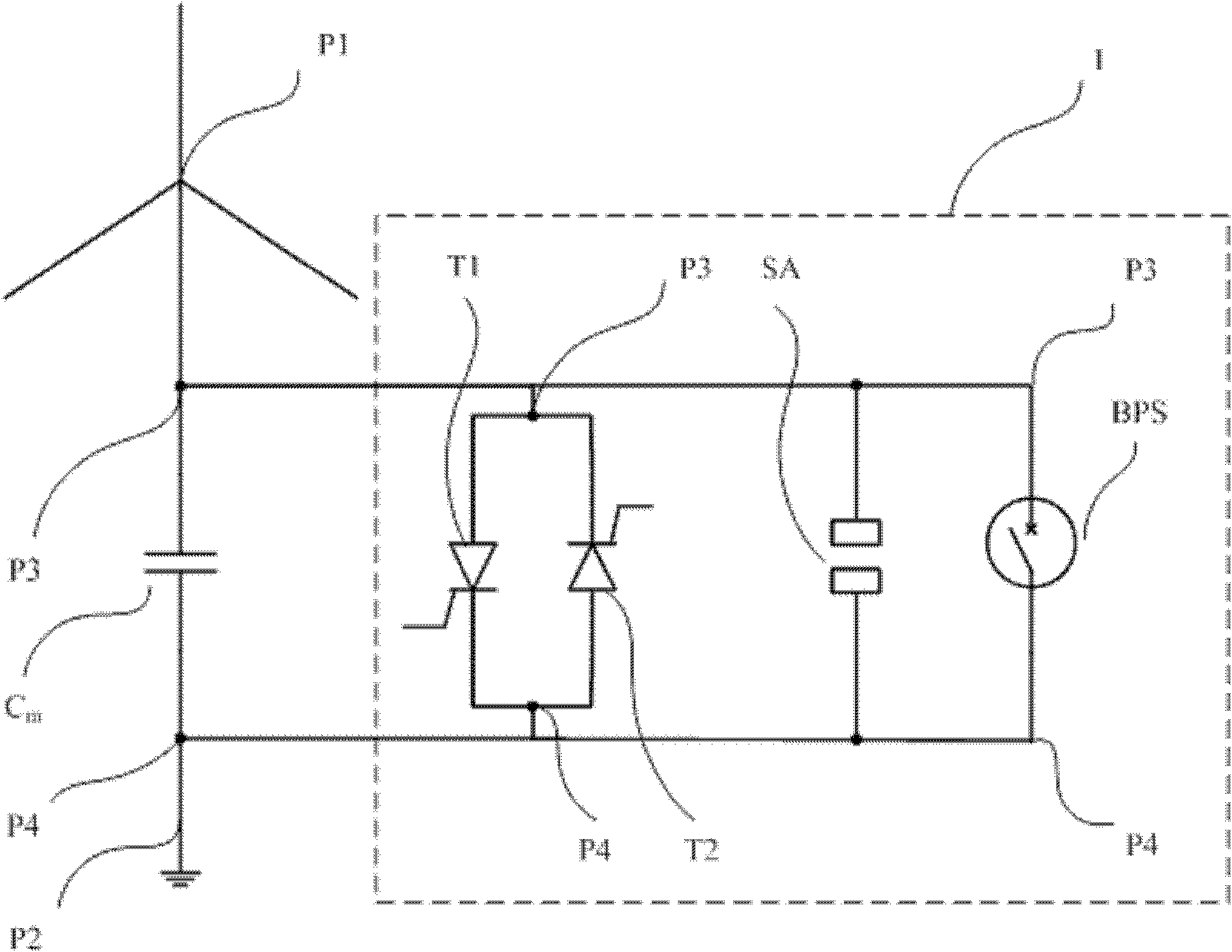
[0023] According to an embodiment of the present invention, the fast bypass device 1 such as figure 1 It includes a pair of anti-parallel thyristors T1 and T2, a lightning arrester SA and a backup protection switch BPS, wherein the anti-parallel thyristors T1 and T2, lightning arrester SA and backup protection switch BPS are connected in parallel with each other at potential points P3 and P4 between. The backup protection switch BPS has a strong ability to withstand high current and can be closed within 1 millisecond after a fault occurs. A backup protective switch BPS is available for example from HVDC PLUS from Siemens and SVC PLUS obtained from the product. Once a pair of anti-parallel thyristors T1 and T2 used as a bypass circuit cannot be bypassed due to a fault, the arrester SA can be turned on within a few microseconds to switch the main capacitor C m short circuit. Subsequently, the backup protection switch BPS is closed within 1 millisecond after the fault occu...


PUM


Abstract

The invention relates to a quick bypass device. The quick bypass device comprises a pair of antiparallel thyristors, a lightning arrester and a standby protection switch, wherein the pair of antiparallel thyristors is mutually connected in parallel with the lightning arrester and the standby protection switch. The quick bypass device has the advantages as follows: 1) a pair of thyristors and a matched electronic drive circuit do not need to be configured, so that the cost is saved; 2) a passive form is adopted, so that limitation that whether a power supply works normally or not is eliminated; and 3) the standby protection switch can be closed within 1ms after a fault is caused, and before the standby protection switch is closed, a load passing through the lightning arrester is finite, so that a main capacitor can be more quickly and reliably protected; and due to a lower load, a smaller lightning device is allowed to be selected, so that the space is saved and the cost is further reduced.

Description

technical field [0001] The invention relates to a fast bypass device, in particular to a fast bypass device for a DC isolation device. Background technique [0002] When a high-voltage direct current (HVDC) system is in earth return mode of operation, a DC current flows through the earth and causes a potential change near the ground electrode of the transformer, which in turn creates a DC potential difference between the neutral points of two adjacent transformers. Due to the low resistance value of the AC system, the potential difference also generates a DC current in the AC system via the neutral point of the transformer. If the DC current is too large, the transformer will be saturated and DC bias will occur, which will cause the temperature of the transformer to be too high, increase the harmonics, increase the noise, and even damage the transformer in severe cases. [0003] In order to solve this problem, a capacitor is connected between the neutral point of the transf...

Claims


Application Information

Patent Timeline
IPC IPC(8): H02H9/04
CPCH02H9/041H02M1/08H02H7/22H02H9/06
Inventor 安德烈亚斯・菲利普赵研峰姚吉隆宋英华吴学智
Owner SIEMENS AG
Why Eureka
Try Eureka