
Source electrode driving control circuit and control method thereof

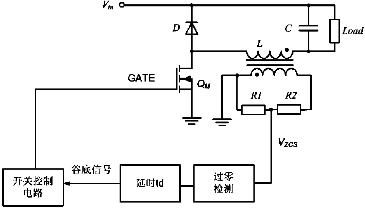
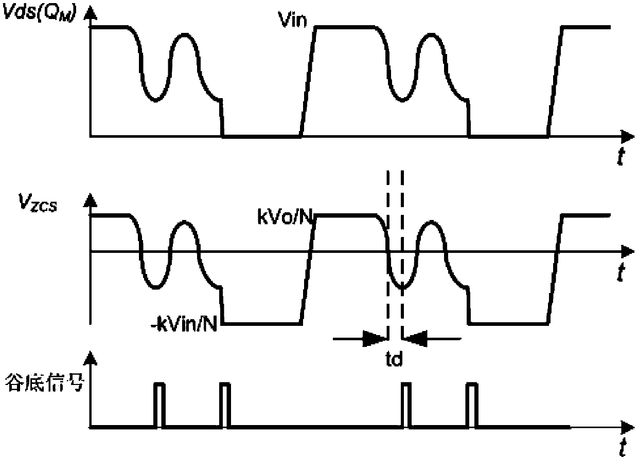
A control circuit and source drive technology, which is applied in the direction of electrical components, high-efficiency power electronic conversion, output power conversion devices, etc., can solve the problems of difficult integration and low precision of quasi-resonant control, and achieve compact chip structure and simple design , Eliminate the effect of the conduction current spike

Active Publication Date: 2014-07-16
SILERGY SEMICON TECH (HANGZHOU) CO LTD
View PDF4 Cites 2 Cited by
  • Summary
  • Abstract
  • Description
  • Claims
  • Application Information

AI Technical Summary

Problems solved by technology

[0005] In view of this, the object of the present invention is to provide a source drive control circuit and its control method, so as to overcome the problems of difficulty in integration and low precision of quasi-resonance control in the prior art due to the existence of auxiliary windings

Method used


Image

  • Source electrode driving control circuit and control method thereof
  • Source electrode driving control circuit and control method thereof
  • Source electrode driving control circuit and control method thereof

Examples


Embodiment 1

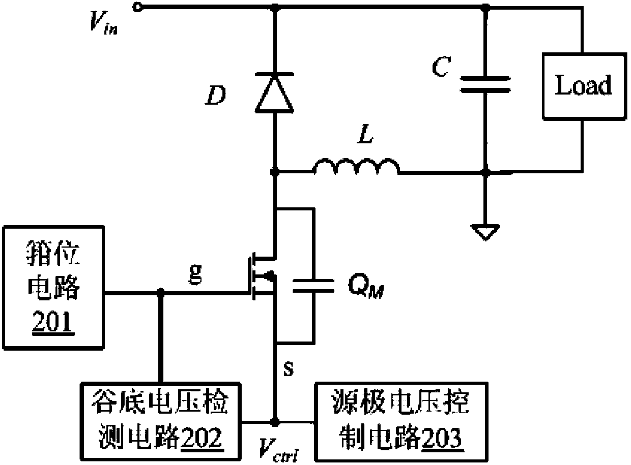
[0103] Preferred embodiment 1: detecting the gate-source voltage, and outputting the valley-bottom control signal at the moment of its negative zero-crossing.

Embodiment 2

[0104] Preferred embodiment 2: Detect the source voltage, and output the valley bottom control signal when it crosses zero in positive direction.

Embodiment 3

[0105] Preferred embodiment 3: performing a differential operation on the source voltage to obtain a differential voltage, and the moment when the drain-source voltage reaches the bottom of the resonance valley corresponds to the moment when the differential voltage positively crosses zero;

[0106] Accepting the differential voltage, outputting the valley bottom control signal when it crosses zero in positive direction.


PUM


Abstract

Disclosed are driving control methods and circuits for quasi-resonant control of a main power switch of a switching power supply. In one embodiment, a driving control circuit can include: (i) a clamp circuit coupled to a gate of the main power switch, where the clamp circuit is configured to clamp a voltage of the gate to a clamping voltage that is greater than a threshold voltage of the main power switch; (ii) a valley voltage detection circuit configured to activate a valley control signal when a drain-source voltage of the main power switch is at a resonance valley level; and (iii) a source voltage control circuit configured to reduce a voltage of a source of the main power switch to turn on the main power switch in response to the valley control signal being activated.

Description

technical field [0001] The invention relates to a quasi-resonance control circuit, in particular to a source drive control circuit and a control method thereof. Background technique [0002] The high frequency of switches is an important direction for the development of modern switching power supplies. The reason is that the high frequency of switches can greatly reduce the volume and weight of switching converters, thereby increasing the power density of the converters. To achieve high frequency, switching loss must be reduced, and soft switching technology is one of the important methods to reduce switching loss. Through the principle of resonance, the voltage or current of the switching tube in the switching converter changes according to the sinusoidal or quasi-sinusoidal law. When the voltage naturally crosses zero, the switching device is turned on; when the current naturally crosses zero, the switching device is turned off, thereby Realize zero switching loss and inc...

Claims


Application Information

Patent Timeline
Patent Type & Authority Patents(China)
IPC IPC(8): H02M1/08H02M1/00
CPCH02M1/00Y02B70/1491H02M1/08H02M3/155H02M2001/0058Y02B70/10H02M1/0058
Inventor 邓建赵晨黄秋凯
Owner SILERGY SEMICON TECH (HANGZHOU) CO LTD
Learn More