Lower support type magnetic levitation device with integrated rotating system
A magnetic levitation and magnetic levitation technology, applied in the direction of the magnetic attraction or thrust holding device, electrical components, etc., can solve the problems of high cost, overturning, system instability, etc., and achieve stable and reliable magnetic levitation, simple structure, and excellent vision Effect
- Summary
- Abstract
- Description
- Claims
- Application Information
AI Technical Summary
Problems solved by technology
Method used
Image

Examples
Embodiment 1
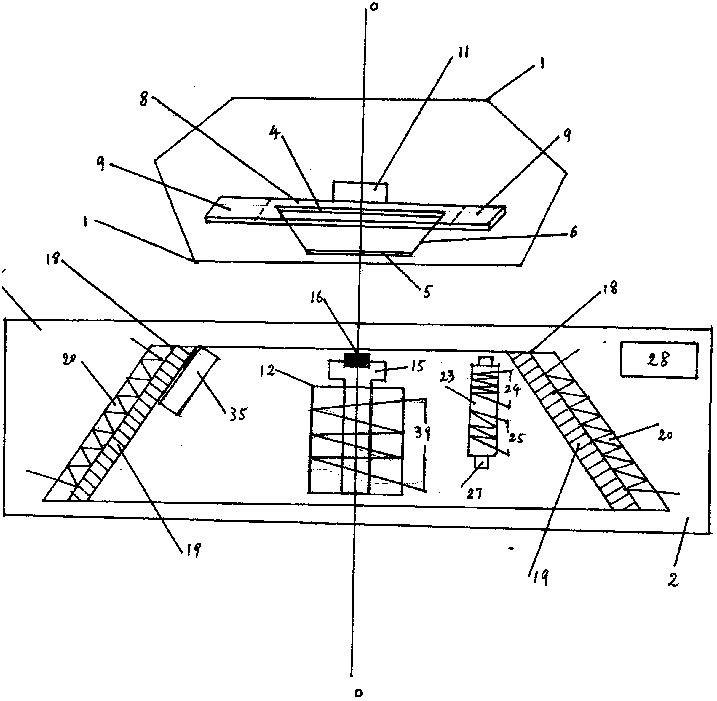
[0014] Embodiment 1: The structure of the undercarriage type magnetic levitation device adopting the integrated rotation system See: figure 1
[0015] The maglev rotating body 1 is magnetically levitated at the center line O above the lower box body 2 and rotates automatically in two directions randomly; at the center line of the lower part of the maglev rotating body 1, a bottom-supporting magnetic levitation permanent magnet 3 is installed, which is large on the top and small on the bottom. Inverted conical shape, its 3 upper magnetic pole surface 4 is larger than the lower magnetic pole surface 5 and has an inclined magnetic surface 6, on the upper magnetic pole surface 4, a rectangular magnetically conductive iron plate 8 is centrally mounted, and its 8 lateral direction The width is greater than the upper magnetic pole surface 4, and there is respectively an outgoing edge 9 of the magnetic guide plate 8 on both sides of its 4, and its 9 has the same magnetism as the upper...
Embodiment 2
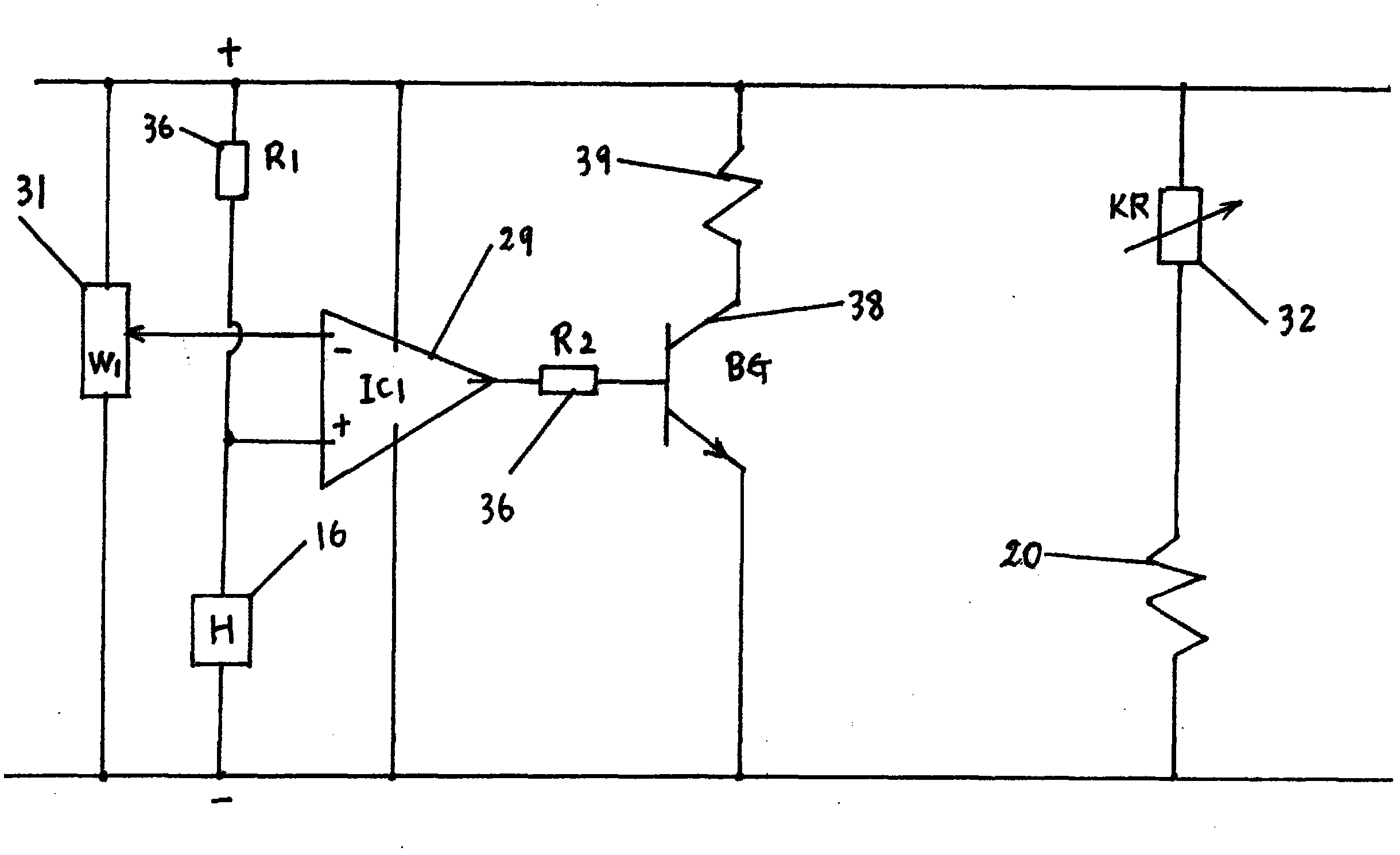
[0017] Embodiment 2: Maglev circuit of maglev system See: figure 2
[0018] In the maglev circuit, the positive power supply is connected to the Hall element 16 (H) through the resistor 36 (R1), the positive input terminal of IC1 of the integrated operational amplifier 29 is connected to the Hall element 16 (H), and the negative input terminal of its 29 is connected to the potential Device 31 (W1), after being amplified by comparison and subtraction, the output of its 29 is connected to the base of the triode 38 (BG) through a resistor 36 (R2) for power amplification, and the collector of its 38 is connected to the electromagnet coil 39 and connected to the current , the electromagnet 12 sends out the heteromagnetic electromagnetic field, so that the maglev rotating body 1 is subjected to the centering force of the downward suction, and the potentiometer 31 adjusts the electric current of the electromagnet coil 39 and the magnitude of the downward suction force of the centeri...
Embodiment 3
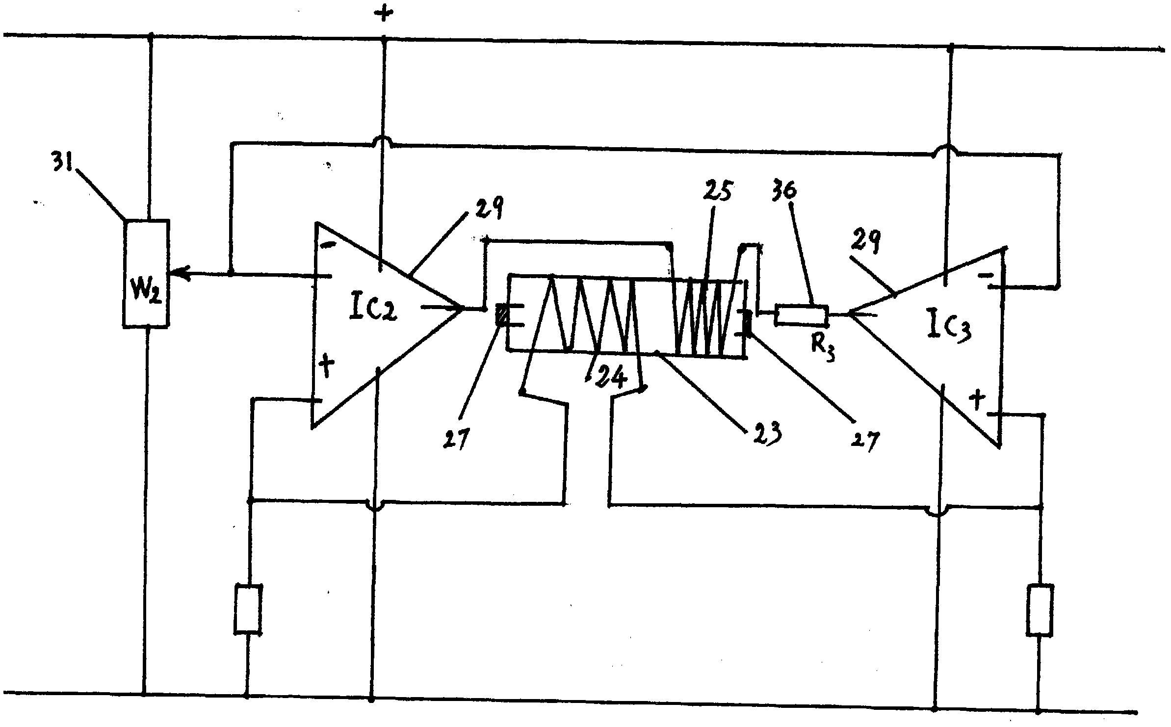
[0019] Embodiment 3: Bidirectional automatic rotating bridge control circuit with integrated rotating system See: image 3
[0020] IC2 and IC3 of the integrated operational amplifier 29 complementarily form a bridge control circuit, the two ends of the magnetic induction coil 24 of the assembly 23 are connected to the positive input terminals of IC2 and IC3, and the negative input terminals of IC1 and IC2 are all connected to the potentiometer 31 (W2). IC1 and IC1 carry out complementary " reverse amplification ", and the output of IC1 and IC2 connects rotating electromagnetic coil 25 through current-limiting resistance 36 (R3), and it 25 obtains the electric current of alternating positive and negative and sends the electromagnetic field of alternating electromagnetic polarity , so that the outgoing side 9 of the iron plate 8 as a rotating magnetic part and the magnetic levitation rotating body 1 obtain the alternating rotational force of pushing and repelling and do two-way...
PUM
 Abstract
Description
Claims
Application Information
 - R&D
- Intellectual Property
- Life Sciences
- Materials
- Tech Scout
- Unparalleled Data Quality
- Higher Quality Content
- 60% Fewer Hallucinations
Browse by: Latest US Patents, China's latest patents, Technical Efficacy Thesaurus, Application Domain, Technology Topic, Popular Technical Reports.
© 2025 PatSnap. All rights reserved.Legal|Privacy policy|Modern Slavery Act Transparency Statement|Sitemap|About US| Contact US: help@patsnap.com