Bearing element

A technology of supporting components and ring components, which is applied in the direction of bearing components, engine components, bearings, etc., can solve the problems of high failure cost, long failure time, difficult access cost of equipment, etc., and achieve the effect of reducing maintenance work and reducing downtime

Active Publication Date: 2012-12-19
MIBA SINTER AUSTRIA
View PDF8 Cites 12 Cited by
  • Summary
  • Abstract
  • Description
  • Claims
  • Application Information

AI Technical Summary

Problems solved by technology

Compared with other faults of wind power plants, a completely different situation arises with regard to costs, in that faults in the bearing structure of the rotor shaft result in significantly higher costs than other common faults of wind power plants and stop time
Despite the reinforcement technology "rolling bearings", especially bearing failures in the multi-megawatt range significantly reduce the economi

Method used


Image

  • Bearing element
  • Bearing element
  • Bearing element

Examples


Embodiment Construction

[0042] First of all, it should be understood that the disclosure contained in the entire specification can be borrowed from the same component or the same component reference numeral in a sense. The position descriptions selected in the description, such as "up", "down", "side", etc., are related to the directly described and shown drawings, and can be borrowed to a new position in a meaningful way when the position changes. Furthermore, individual features or combinations of features of the different embodiments shown and described can also be independent solutions according to the invention.

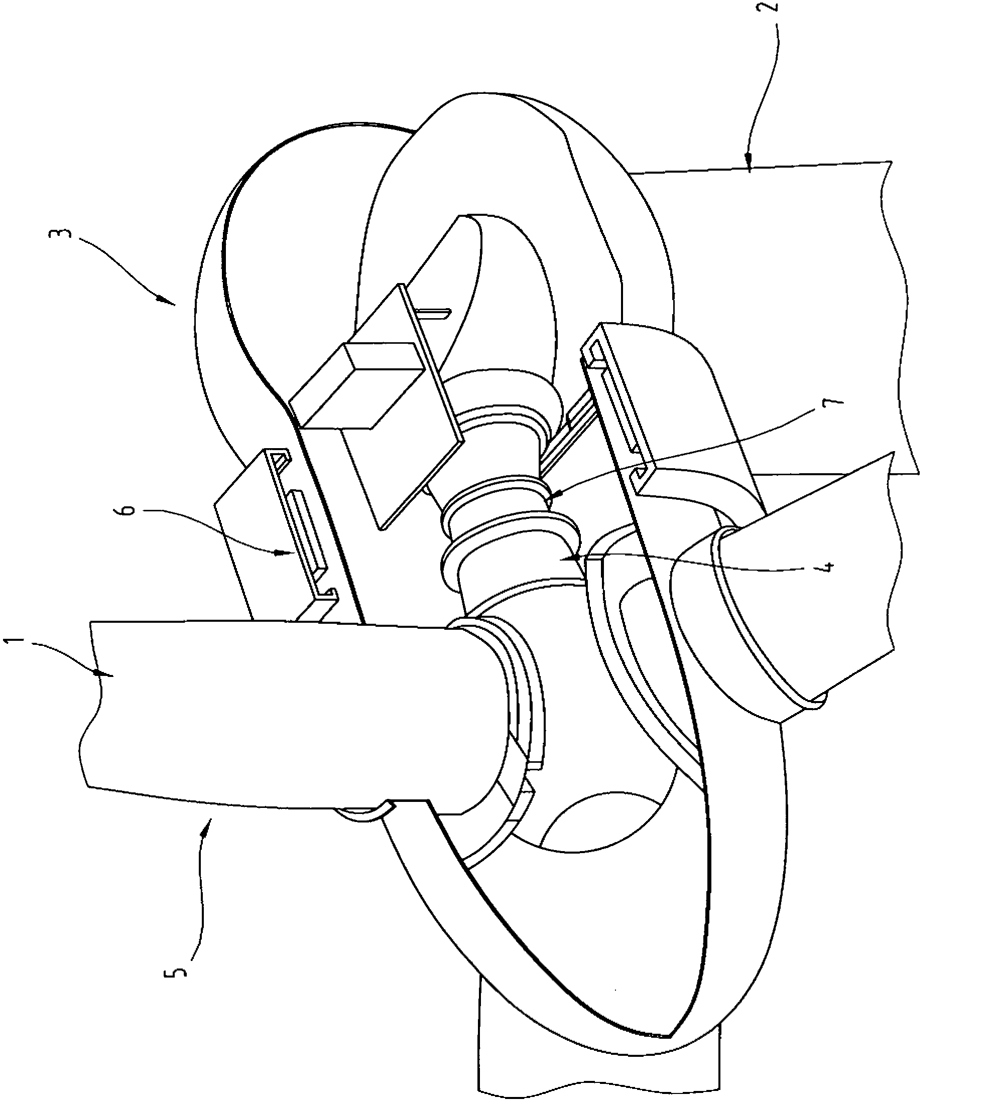
[0043] figure 1 A part of the wind power plant 1 is shown in an oblique view and partly cut away, as it is known in principle from the prior art. The wind power plant 1 includes a tower 2 with a nacelle 3 arranged on the tip of the tower. A rotor hub 4 is arranged in this pod 3, said rotor hub carrying rotor blades 5 on one end thereof, in particular in a rotatable manner. In order to g...


PUM


Abstract

The invention relates to a bearing element (7) for supporting the rotor hub (4) of a wind turbine (1), comprising at least one inner ring element (10, 40) and at least one outer ring element (11, 41), wherein a plain bearing support is developed between the inner ring element (10, 40) and the outer ring element (11, 41), and wherein the plain bearing support is formed by at least two plain bearings (8, 9, 38, 39) arranged at an axial distance (44) from each other.

Description

Technical field [0001] The present invention relates to a support element for supporting a rotor hub of a wind power plant. The support element has at least one inner ring element and at least one outer ring element, wherein between the inner ring element and the outer ring element A sliding support structure is formed between the rotor, and the present invention relates to a wind power generation device with a rotor, the rotor has a rotor hub, the rotor hub is supported on the stator, wherein between the rotor and the stator is arranged Support element. Background technique [0002] Although sliding bearings have a significantly longer service life than rolling bearings, rolling bearings are still mainly used in wind power generation equipment, especially as main bearings for supporting the rotor. Various studies on wind power equipment have shown that, in addition to other different causes of failure in the area of ​​the generator or rotor blade itself or the rotor, the cause ...

Claims


Application Information

Patent Timeline
IPC IPC(8): F03D11/00F16C23/02
CPCF16C17/10Y02E10/722Y02E10/72F03D11/0008F03D80/70F16C2300/14F16C2360/31F16C2237/00F16C2226/70F16C2226/76
Inventor A·卡里C·弗斯特纳
Owner MIBA SINTER AUSTRIA
Why Eureka
Try Eureka