
Cutting anastomat for surgical operation

A technique for surgical operation and stapler, which is applied in the directions of surgery, surgical fixation nails, and applications, can solve the problems of bleeding, difficulty in cutting staplers entering the male pelvis, and poor staple formation, and achieves convenient use, smooth and reliable delivery, and high reliability. The effect of improving safety

Active Publication Date: 2012-12-26
CHANGZHOU KANGDI MEDICAL STAPLER
View PDF6 Cites 25 Cited by
  • Summary
  • Abstract
  • Description
  • Claims
  • Application Information

AI Technical Summary

Problems solved by technology

[0004] When performing cutting and anastomosis, surgeons often face many challenges when it is difficult to expose the operative field, such as: ① It is difficult for the cutting stapler to enter the lower part of the male pelvis; When the clamped tissue is not fully inserted into the positioning hole of the liner, after being squeezed by the jaws of the cutting stapler, overflow will occur at the opening end of the jaws, which will cause poor formation of the staples and partially overflow The tissue has not been sutured, and if the tissue is cut at this time, it will cause bleeding; ③In the lower pelvic cavity, after the tissue is sutured, there is no extra space for manual cutting; ④How to facilitate the operation, reduce the chance of infection, and reduce the risk of tissue damage Trauma, increasing the safety of surgery, etc.
[0005] The existing cutting staplers still have deficiencies in terms of working reliability, operation convenience and surgical safety, and need to be further improved

Method used


Image

  • Cutting anastomat for surgical operation
  • Cutting anastomat for surgical operation
  • Cutting anastomat for surgical operation

Examples


Embodiment Construction

[0039] The present invention will be described in further detail below in conjunction with the accompanying drawings and specific embodiments, so that those skilled in the art can more clearly understand other advantages and effects of the present invention.

[0040]It should be noted that the structures, proportions, sizes, etc. shown in the drawings of the specification are only used to cooperate with specific implementation methods, so that those skilled in the art can understand the concept of the present invention more clearly, and are not intended to limit the scope of protection of the present invention. . Any structural modification, change in proportional relationship or size adjustment should still fall within the protection scope of the present invention, provided that it does not affect the function and purpose of the present invention. For ease of description, the relative positional relationship of each component is described according to the layout of the drawin...


PUM


Abstract

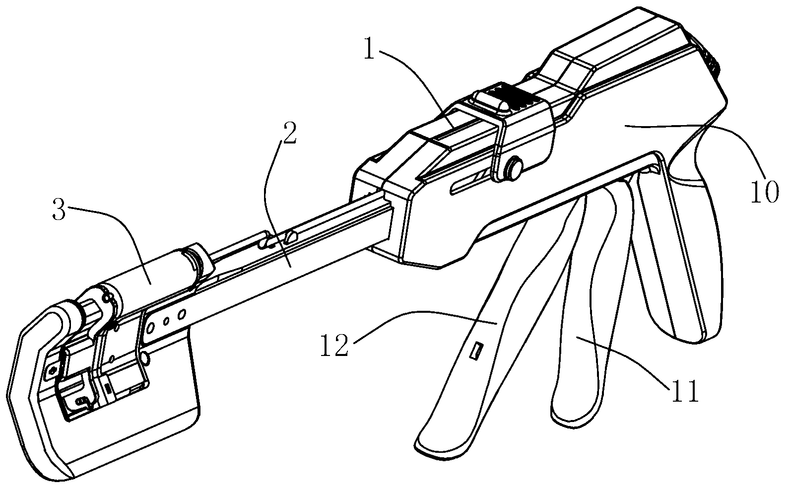
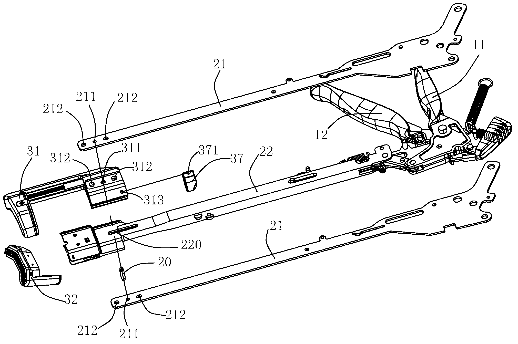
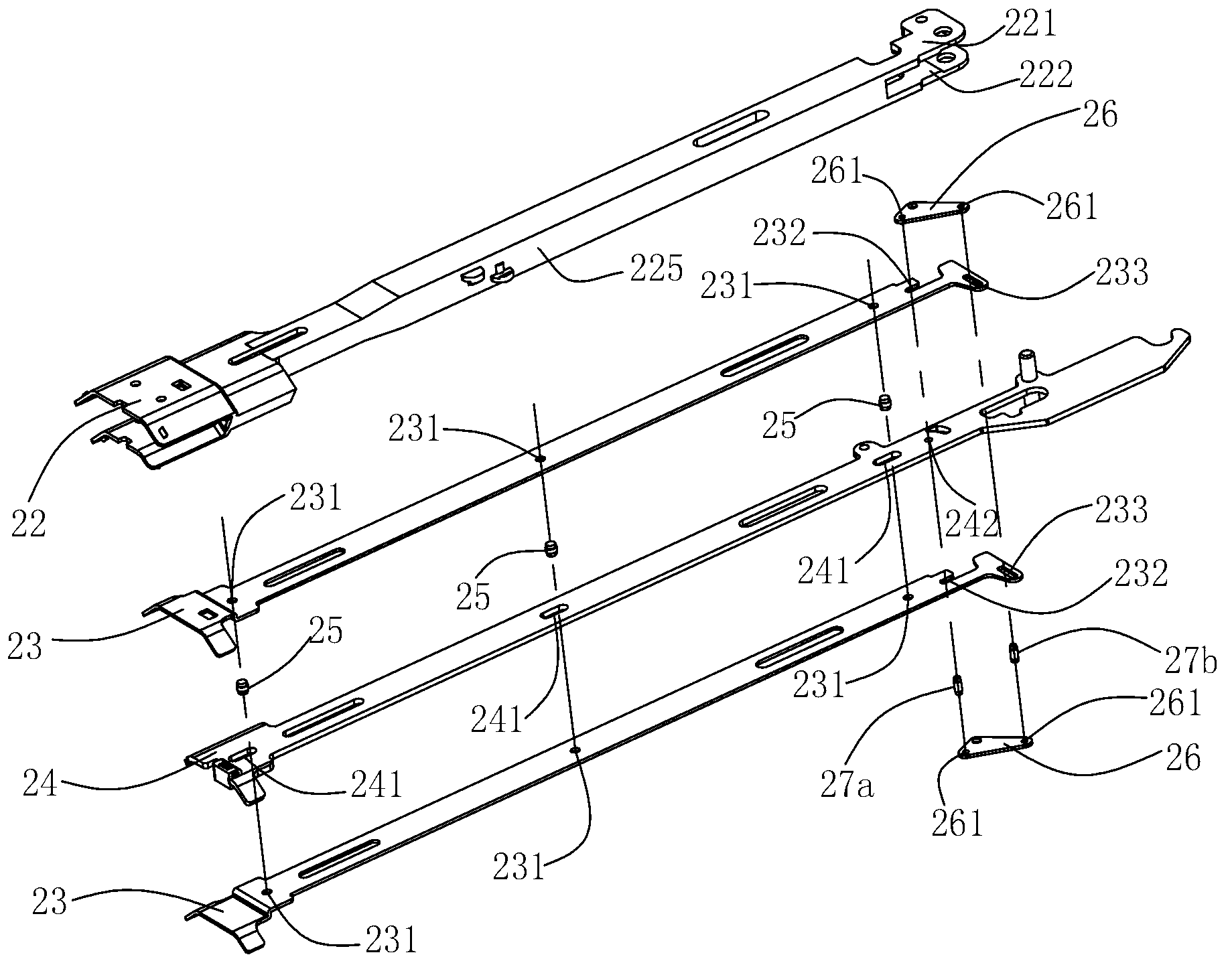
The invention discloses a cutting anastomat for surgical operation. The cutting anastomat comprises an operation component, a support component and an executing component, wherein the operation component comprises a case, a closed handle and a firing handle, the executing component comprises a seat frame, a nail cabin, a nail pushing sheet and a cutting knife, the seat frame is provided with a tong jaw, the support component comprises a main push plate, two sub push plates, two connecting plates and two support frame plates, the front end of the main push plate is connected with the cutting knife, the back end of the main push plate is connected with the firing handle, the two sub push plates are respectively positioned at the left side and the right side of the main push plate, the front ends of the sub push plates are in contact with the nail pushing sheet, the main push plate and the sub push plates are clamped between the left wall plate and the right wall plate of the side plate, the front end of the side plate is connected with the nail cabin, the back end of the side plate is connected with the closed handle, the two support frame plates are positioned at the left side and the right side of the side plate, the front ends of the support frame plates are fixedly connected with the seat frame, the back ends of the support frame plates are fixedly connected with the case. The cutting anastomat provided by the invention has the advantages that the action is more reliable, and the use is safer.

Description

technical field [0001] The invention relates to a surgical medical instrument, in particular to a cutting stapler. Background technique [0002] In cutting and anastomotic operations, the use of cutting and staplers can reduce operation time and improve operation quality. Chinese invention patent application CN102599954A discloses a linear cutting stapler with double safety mechanism, which includes a closing safety mechanism, a firing safety mechanism, a left side plate, a partition, a drive plate, a liner, a right side plate, a shell, a closing Handle, firing handle part, left bracket plate and right bracket plate; the linear cutting stapler can load or remove the linear cutting element; the closing safety mechanism includes push button, thimble seat, pin one, closing safety part , torsion spring and thimble; the closing safety part is connected with the torsion spring through a pin, and the hook on the closing safety part prevents the movement of the partition through th...

Claims


Application Information

Patent Timeline
IPC IPC(8): A61B17/072
CPCA61B17/072A61B2017/00738A61B2090/08021
Inventor 芮龙吉荣虞国安戴晓东袁栋坤
Owner CHANGZHOU KANGDI MEDICAL STAPLER
Learn More