
Optical member adhering method, and apparatus using the method

A lamination device and lamination technology, applied in optical components, optical components, chemical instruments and methods, etc., can solve problems such as poor quality, and achieve the effect of maintaining quality, high quality, and reducing dust adhesion

Active Publication Date: 2015-02-18
NITTO DENKO CORP
View PDF4 Cites 0 Cited by
  • Summary
  • Abstract
  • Description
  • Claims
  • Application Information

AI Technical Summary

Problems solved by technology

Furthermore, for the board|substrate used in the conventional apparatus, in order to convey and handle it to the next step under the state where the photosensitive resin layer was exposed, so there also exists the following problem especially, that is, dust adheres to the surface and produces poor quality

Method used


Image

  • Optical member adhering method, and apparatus using the method
  • Optical member adhering method, and apparatus using the method
  • Optical member adhering method, and apparatus using the method

Examples


Embodiment Construction

[0089] Embodiments of the present invention will be described below with reference to the drawings. In addition, in the present invention, the optical member is not particularly limited as long as it is a flexible strip-shaped functional film such as a polarizing film, a retardation film, or a brightness improvement film. In this embodiment, the case where a polarizing film is used is taken as an example and described. In addition, the monolithic body of the present invention is not particularly limited as long as it is a functional film such as a polarizing film, a retardation film, and a brightness-enhancing film, a polarizing plate, and a liquid crystal panel. In this embodiment, a liquid crystal panel is used as an example for description. .

[0090]In addition, both the separation film and the protective film of the present invention cover and protect an optical member or a polarizing film in order to prevent surface damage and the like. Here, the separation film can be...


PUM

PropertyMeasurementUnit
wavelengthaaaaaaaaaa

Abstract

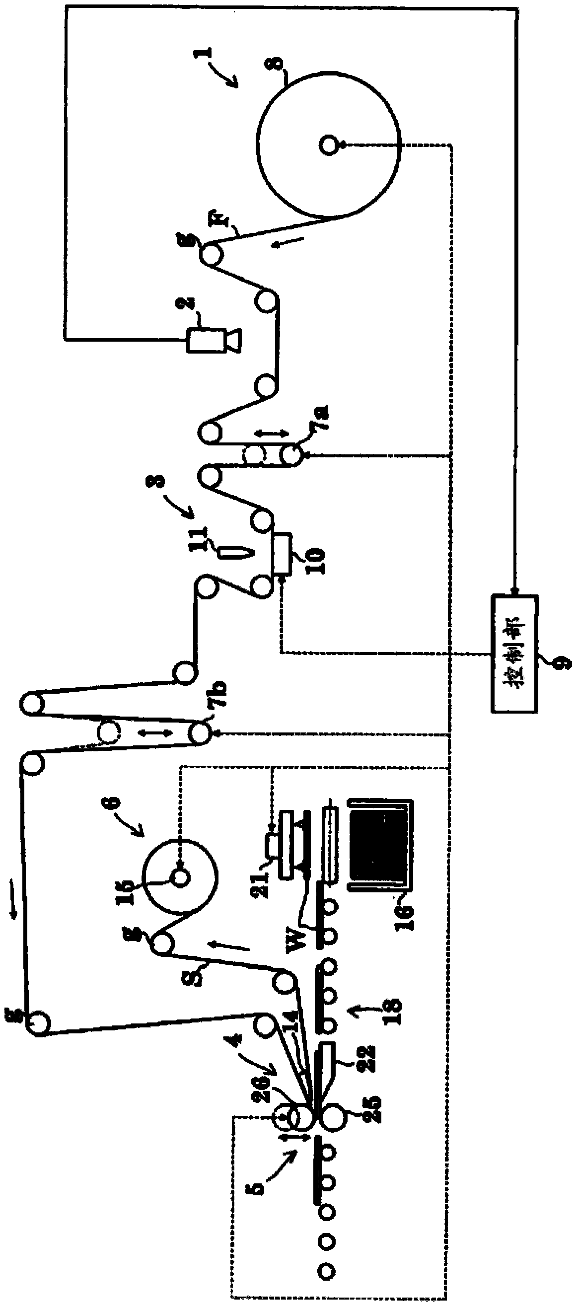
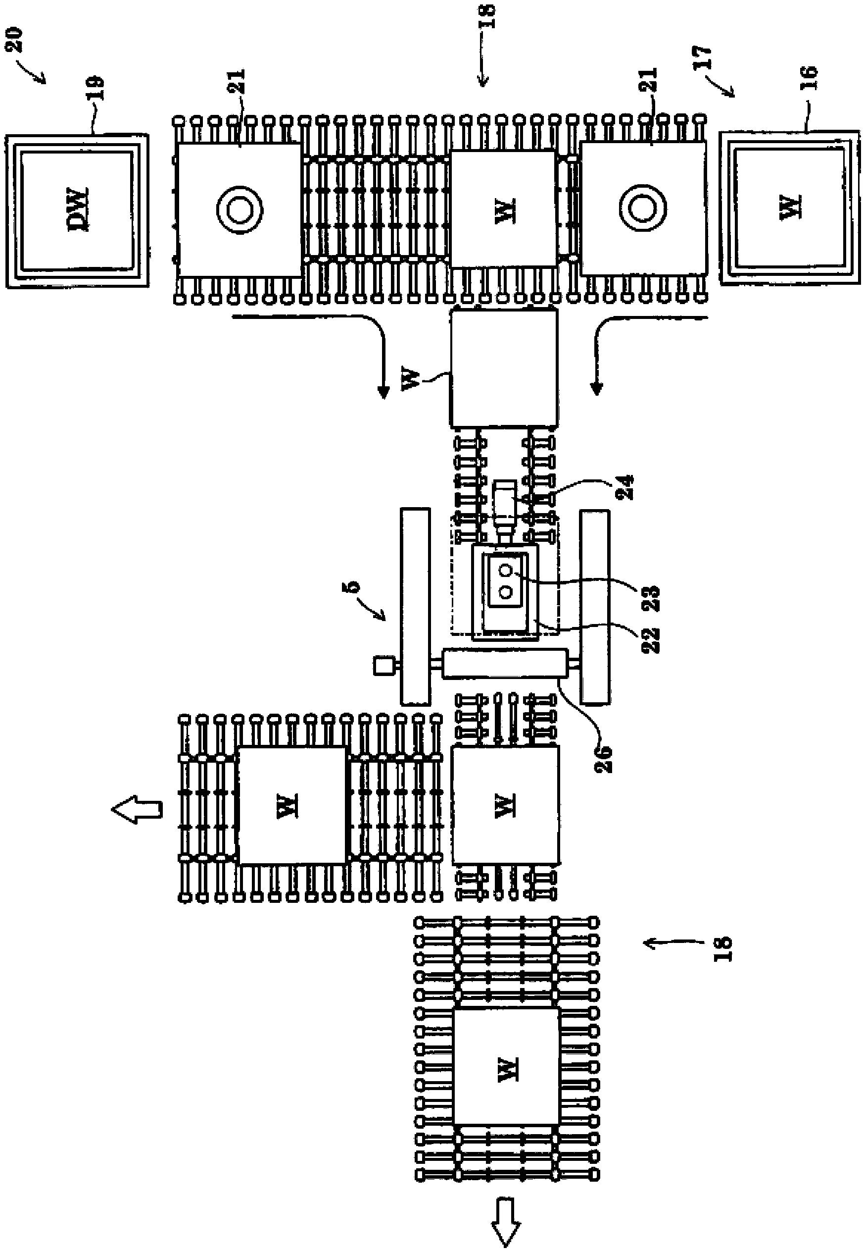
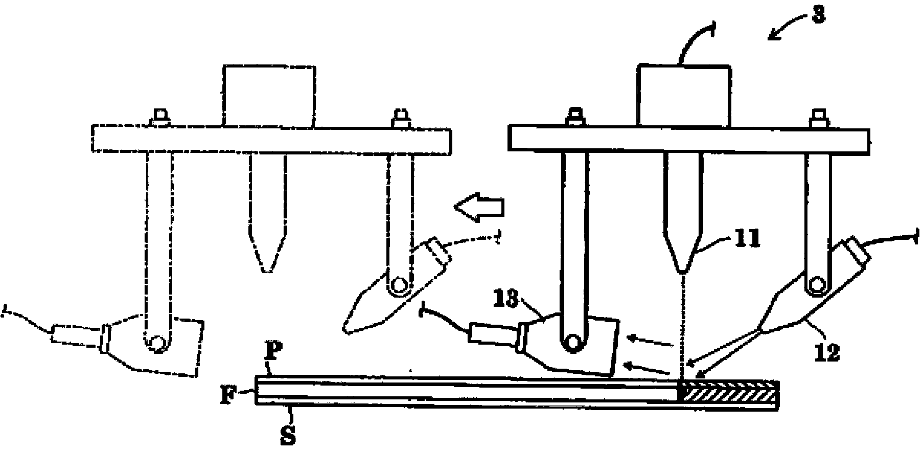
[Objects] To make it possible to carry out automatically and accurately a laminating operation of an optical element to a sheet-shaped body. [Means for Accomplishing the Objects] A strip-shaped polarizing film has a protective film strip conformably adhered to one surface thereof and a releasable liner conformably adhered to the other surface thereof and delivered from a film delivering station 1. After an appearance inspection, a lamination of the protective film strip and the polarizing film strip F is half-cut using a laser unit 11 to form an array of laminations each consisting of a protective film and a polarizing film F, with the releasable liner being left intact. Then, the polarizing films F are fed to a peeling mechanism 4. The peeling mechanism 4 feeds a forwardmost one the polarizing films F to a laminating mechanism 5 while peeling off the releasable liner therefrom by a knife-edged member. The forwardmost polarizing film F is laminated to a liquid-crystal panel W conveyed to the laminating mechanism by a panel transport apparatus 18 in synchronization of the feeding of the forwardmost polarizing film F.

Description

[0001] This application is a divisional application of the patent application for invention filed by Nitto Denko Co., Ltd. on October 12, 2007, entitled "Optical component bonding method and device using the method" and application number 200780038717.3. technical field [0002] The present invention relates to a lamination method of optical members constituted by laminating optical members such as polarizing films, brightness-enhancing films, and phase difference films automatically, at high speed and with high precision, on a single-piece body such as a liquid crystal panel, and the method using the method. device. Background technique [0003] Conventionally, an optical member and a substrate as a single piece are bonded as follows. Continually transport multiple substrates at a predetermined pitch, and supply a strip-shaped photosensitive laminate film consisting of a photosensitive resin layer and a base film from which the protective film has been peeled off during unl...

Claims


Application Information

Patent Timeline
Patent Type & Authority Patents(China)
IPC IPC(8): B29D11/00B23K26/08B23K26/40B32B38/00B32B41/00G02B5/30G02F1/13G02F1/1333B23K26/38B29C65/48B32B7/02G09F9/00
CPCB23K26/409B32B2307/40B29D11/0073G02F1/133528Y10T156/1056B32B38/0004B32B41/00B32B37/182B32B2457/202B32B2041/04G02F1/1303G02F1/133305Y10T156/1057G01N21/8422B32B2310/0843B23K26/0846B23K2201/16Y10T156/12B32B38/10B23K26/40B32B2305/55B32B2307/42B23K2101/16B23K2103/172G02B5/3016B29C65/78G02B5/30G02F1/13G02F1/1335
Inventor 北田和生龟田祥弘西田干司由良友和天野贵一大桥宏通日野敦司松尾直之
Owner NITTO DENKO CORP
Learn More