
Drill pipe of engineering driller

A technology for engineering drilling rigs and drill pipes, which is applied in the direction of drill pipes, rotary drilling rigs, and drill pipes. Simplicity and the effect of shortening the construction schedule

Inactive Publication Date: 2012-12-26
上海工程机械厂有限公司
View PDF4 Cites 0 Cited by
  • Summary
  • Abstract
  • Description
  • Claims
  • Application Information

AI Technical Summary

Problems solved by technology

This type of engineering drilling rig in the prior art increases the energy of the engineering drilling rig to drill the formation by relying on the weight of the drill pipe, the drilling tool assembly and the weight of the drill bit of the drilling rig during the drilling process of the drilling tool. However, the engineering drilling rig of this structure The drill pipe is heavy and the drilling efficiency is low, especially when the hard rock layer is encountered during the drilling process, the rock-breaking ability of the drilling rig can only be solved by replacing the expensive drill bit or purchasing a more powerful engineering drilling rig. This will cause high cost to the construction unit and affect the efficiency of construction operations.

Method used


Image

  • Drill pipe of engineering driller
  • Drill pipe of engineering driller

Examples


Embodiment 1

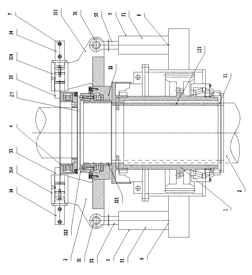
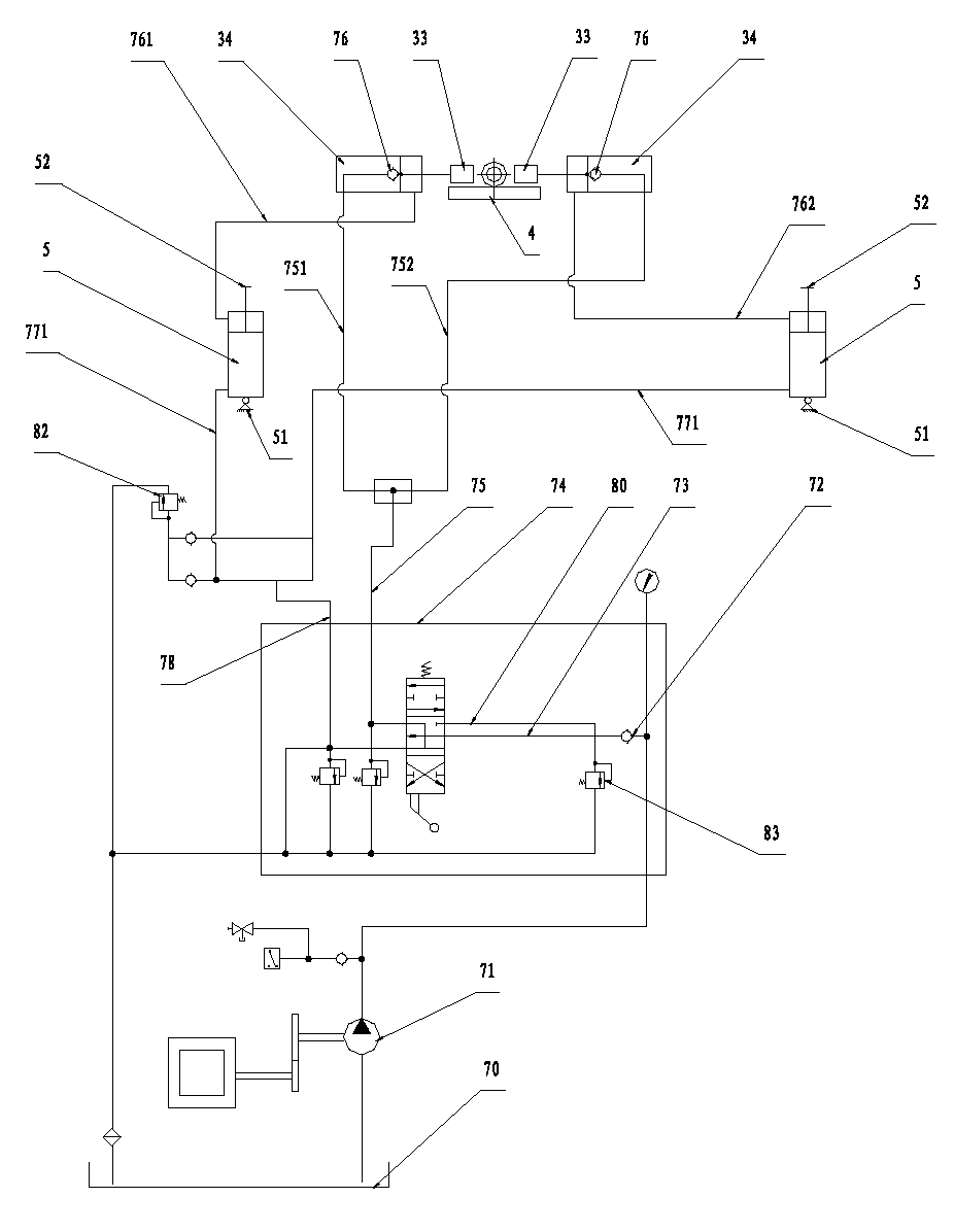
[0021] The manual reversing valve 74 moves upwards, the hydraulic pump 71 takes the hydraulic oil in the hydraulic oil tank 70, passes through the first check valve 72, the oil inlet pipe 73 and the manual reversing valve 74, the first working oil pipe 75, and the first oil distribution pipe 751 2. The second oil distribution pipe 752 provides hydraulic oil to the large chambers of the two pressure rod cylinders 5, and the pressure rod 33 stretches out from the cylinder 314 to press the drill pipe fixing ring 4. When the pressure oil in the large chambers of the two pressure rod cylinders 5 reaches the first When the second one-way valve 76 opens the pressure, the hydraulic oil enters the small cavity of the two lift cylinders 5 through the third oil distribution pipe 761 and the fourth oil distribution pipe 762, and the piston rod 52 of the lift cylinder 5 shrinks and pulls down the press frame 3, and 2 Drill down and excavate under pressure.


PUM


Abstract

A drill pipe of an engineering driller comprises a power driving plate, a drill pipe, a press frame, a drill pipe fixing ring, two lifting oil cylinders, an underframe and a hydraulic system; the drill pipe of the engineering driller is characterized in that the upper part of the drill pipe is provided with a mounting flange; the press frame is positioned above a driving sleeve; the drill pipe penetrates through a hole of a drill pipe press frame; the mounting flange of the drill pipe is fixedly mounted on the upper end surface of the drill pipe press frame; the drill pipe fixing ring is mounted in a sleeving manner at the upper part of the drill pipe, which extends out of the end surface of the mounting flange; the two lifting oil cylinders are fixedly mounted on left and right sides of the underframe in a vertical and symmetric way; piston rods of the two lifting oil cylinders are connected with the press frame; piston rods of two press rod oil cylinders are connected with press rods; a hand-directional valve in the hydraulic system can be used for changing the flowing direction of hydraulic oil, so that the piston rods of the lifting oil cylinders are pulled downwards and jacked upwards; the piston rods of the press rod oil cylinders extend out and retract, so as to respectively apply a pressure to the press frame and release the pressure of the press frame; and the drill pipe is used for drilling in pressurized and normal states; and according to the invention, through the adoption of a drill pipe fixing ring structure, the stability and drilling capability of the engineering driller in operation are improved, the construction efficiency of the driller is increased, and the construction progress is reduced.

Description

technical field [0001] The invention relates to a drill rod, more precisely, to a drill rod for an engineering drilling rig. Background technique [0002] At present, in the construction of highways, railways, bridges, high-rise buildings, ports and dams, large-diameter cast-in-place piles are widely used in pile foundation construction, and there is a further market demand for large-diameter cast-in-situ pile engineering drilling. This type of engineering drilling rig in the prior art increases the energy of the engineering drilling rig to drill the formation by relying on the weight of the drill pipe, the drilling tool assembly and the weight of the drill bit during the drilling process of the drilling tool. However, the engineering drilling rig of this structure The drill pipe is heavy and the drilling efficiency is low, especially when the hard rock layer is encountered during the drilling process, the rock-breaking ability of the drilling rig can only be solved by repla...

Claims


Application Information

Patent Timeline
Patent Type & Authority Applications(China)
IPC IPC(8): E21B17/00E21B19/08F15B11/16
Inventor 王文清张慧颖陈文澜张鹏
Owner 上海工程机械厂有限公司
Learn More