Temperature rise test method and system for electrically excited synchronous motors

A synchronous motor, temperature rise test technology, applied in the electrical field, can solve the problems of no test device or system, low flexibility, high cost, etc.

Inactive Publication Date: 2012-12-26
CSR ZHUZHOU ELECTRIC LOCOMOTIVE RES INST
View PDF9 Cites 6 Cited by
  • Summary
  • Abstract
  • Description
  • Claims
  • Application Information

AI Technical Summary

Problems solved by technology

[0004] However, if this method is used for the temperature rise test of an electrically excited synchronous motor, each time a temperature rise test is performed on an electrically excited synchronous motor, it is necessary to set up a companion motor whose power and working range are larger than the tested motor. When the temperature rise test

Method used


Image

  • Temperature rise test method and system for electrically excited synchronous motors
  • Temperature rise test method and system for electrically excited synchronous motors
  • Temperature rise test method and system for electrically excited synchronous motors

Examples


Example Embodiment

[0056] In order to make the purposes, technical solutions and advantages of the embodiments of the present application clearer, the technical solutions in the embodiments of the present application will be clearly and completely described below in conjunction with the drawings in the embodiments of the present application. Obviously, the described embodiments It is a part of the embodiments of this application, not all of them. Based on the embodiments in this application, all other embodiments obtained by persons of ordinary skill in the art without making creative efforts belong to the scope of protection of this application.

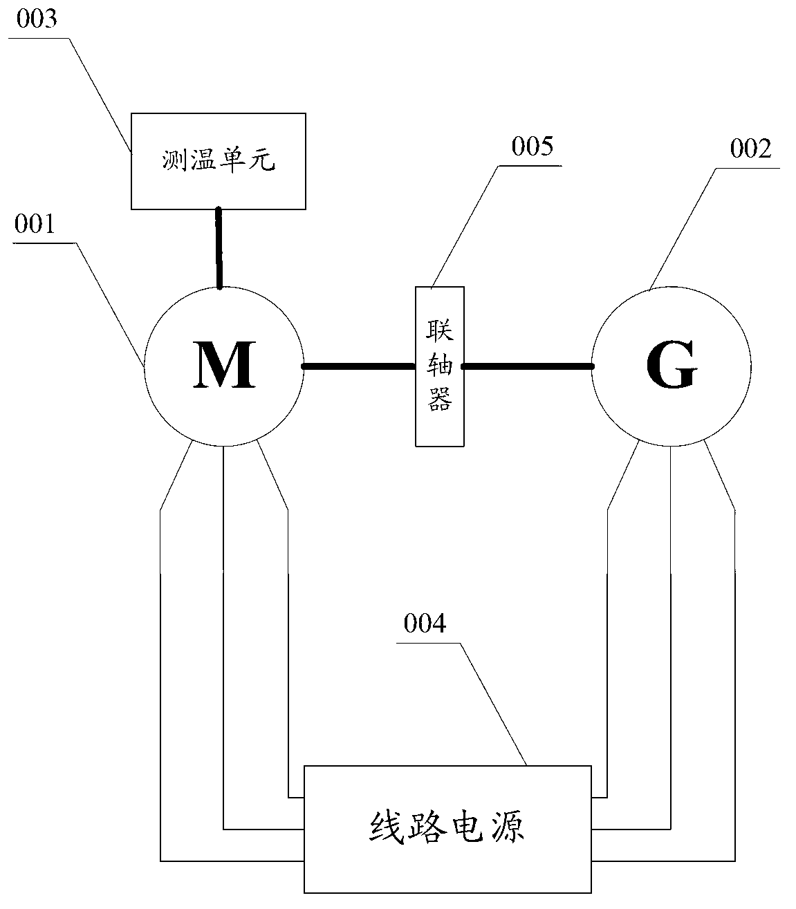
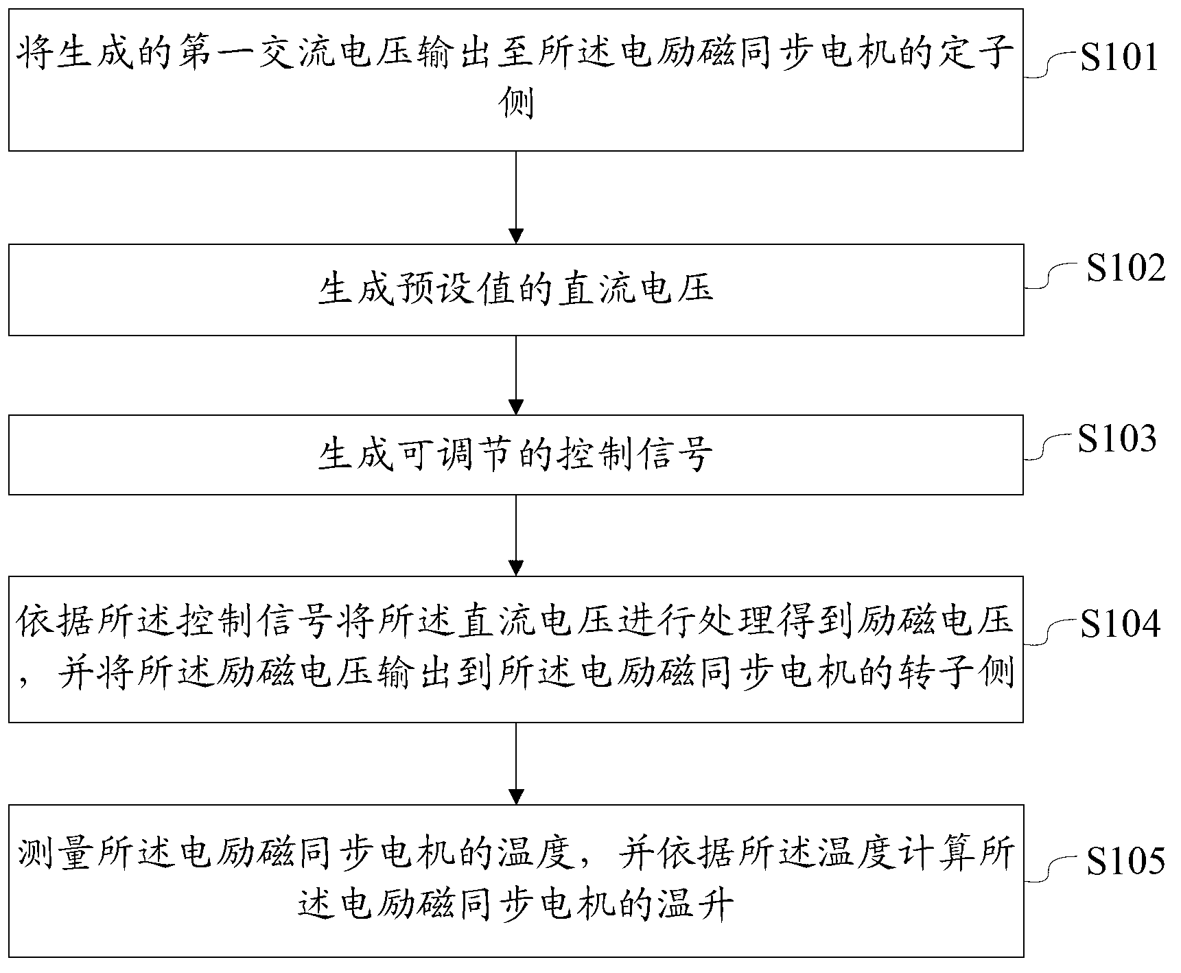
[0057] see figure 2The flow chart of Embodiment 1 of a temperature rise test method for an electrically excited synchronous motor provided by the present application is shown, including:

[0058] Step S101: Outputting the generated first AC voltage to the stator side of the electrically excited synchronous motor;

[0059] The AC voltage provided by...


PUM


Abstract

The application provides a temperature rise test method and system for electrically excited synchronous motors. The temperature rise test method comprises the following steps that: a first alternating current power supply supplies alternating current voltage to a stator side of the motor; a direct current power supply supplies direct current voltage; a controller generates an adjustable control signal; a current transformer processes the direct current voltage according to the control signal to obtain pulse excitation voltage and outputs the pulse excitation voltage to a rotor side of the motor; the control signal is adjusted to ensure that an effective value of alternating current flowing to the tested motor is equal to a rated current value of the motor, and then the motor can be subjected to a temperature rise test; and a temperature measurer calculates the temperature rise of the motor. The controller can adjust the output control signal according to the requirement on the type and the like of the tested synchronous motor, and the temperature rise test system can be used for performing the temperature rise test on the different types of electrically excited synchronous motors, and company test motors are not needed, so that the test working efficiency is high, and the cost is low.

Description

technical field [0001] The application belongs to the electrical field, and in particular relates to a temperature rise test method and system for an electrically excited synchronous motor. Background technique [0002] The temperature rise test of the motor is a test to determine the temperature rise of the motor stator winding, iron core and rotor winding under specified operating conditions. The purpose of the test is to check whether the temperature rise of each effective part of the motor meets the requirements of the standard. [0003] Currently, see figure 1 The system diagram of the test shown includes: the tested motor 001, the accompanying test motor 002, the temperature measurement unit 003, the line power supply 004 and the coupling 005. The power and working range of the accompanying test motor 002 are larger than that of the tested motor 001. The two motors are connected through the coupling 005 and kept in sync. The losses of the two motors are supplied by t...

Claims


Application Information

Patent Timeline
IPC IPC(8): G01R31/34
Inventor 尚敬梅文庆甘韦韦杨大成周志宇江平胡仙
Owner CSR ZHUZHOU ELECTRIC LOCOMOTIVE RES INST
Why Eureka
Try Eureka