
Anti-interference electricity protecting method and anti-interference electricity protecting apparatus for electric equipment

A technology for protection devices and electrical equipment, applied in emergency protection circuit devices, emergency protection devices with automatic disconnection, circuit devices, etc., can solve problems such as inability to correctly identify the cause of low voltage, fault expansion, etc., to avoid sudden start of the motor , Guaranteeing equipment and personal safety, the effect of guaranteeing equipment and personal safety

Active Publication Date: 2012-12-26
BAOWU CHARCOAL MATERIAL TECH CO LTD
View PDF5 Cites 21 Cited by
  • Summary
  • Abstract
  • Description
  • Claims
  • Application Information

AI Technical Summary

Problems solved by technology

[0007] The purpose of the present invention is to provide an anti-sway electric protection method for electrical equipment, so as to solve the problem that the anti-sway electric contactor and the anti-sway electric method that provides UPS uninterruptible power supply to the coil of the AC contactor in the prior art cannot correctly identify the cause of low voltage , unable to quickly trip and cause technical problems of fault expansion

Method used


Image

  • Anti-interference electricity protecting method and anti-interference electricity protecting apparatus for electric equipment
  • Anti-interference electricity protecting method and anti-interference electricity protecting apparatus for electric equipment
  • Anti-interference electricity protecting method and anti-interference electricity protecting apparatus for electric equipment

Examples


Embodiment Construction

[0071] In order to better understand the above technical solutions of the present invention, a further detailed description will be given below in conjunction with the drawings and embodiments.

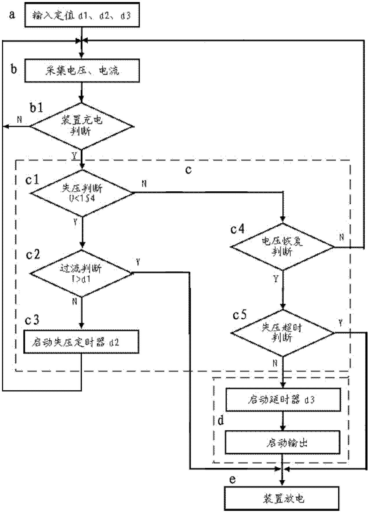
[0072] figure 1 It is the software flow chart of the first embodiment of the method of using computer program control to realize the anti-sway protection method of electric equipment of the present invention. Contains the known program steps required for processes such as power-on initialization of computer software and hardware familiar to those skilled in the art. The basic steps for realizing the anti-sway protection method of electrical equipment provided by the present invention include:

[0073] Step a, the steps for inputting the setting parameters and storing the setting parameters in the storage device:

[0074] The parameters involved in the anti-sway protection of electrical equipment include the low voltage setting value for judging loss of voltage, the overcurrent setti...


PUM


Abstract

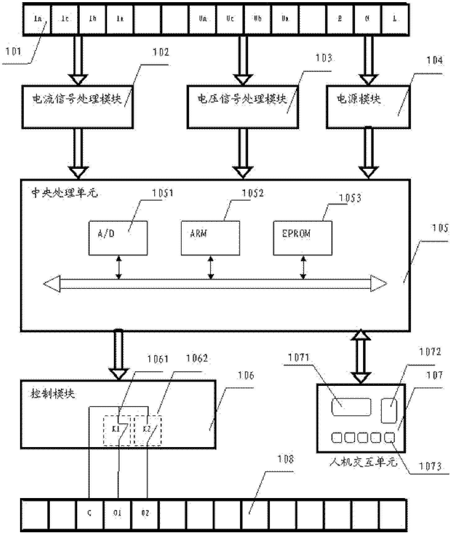
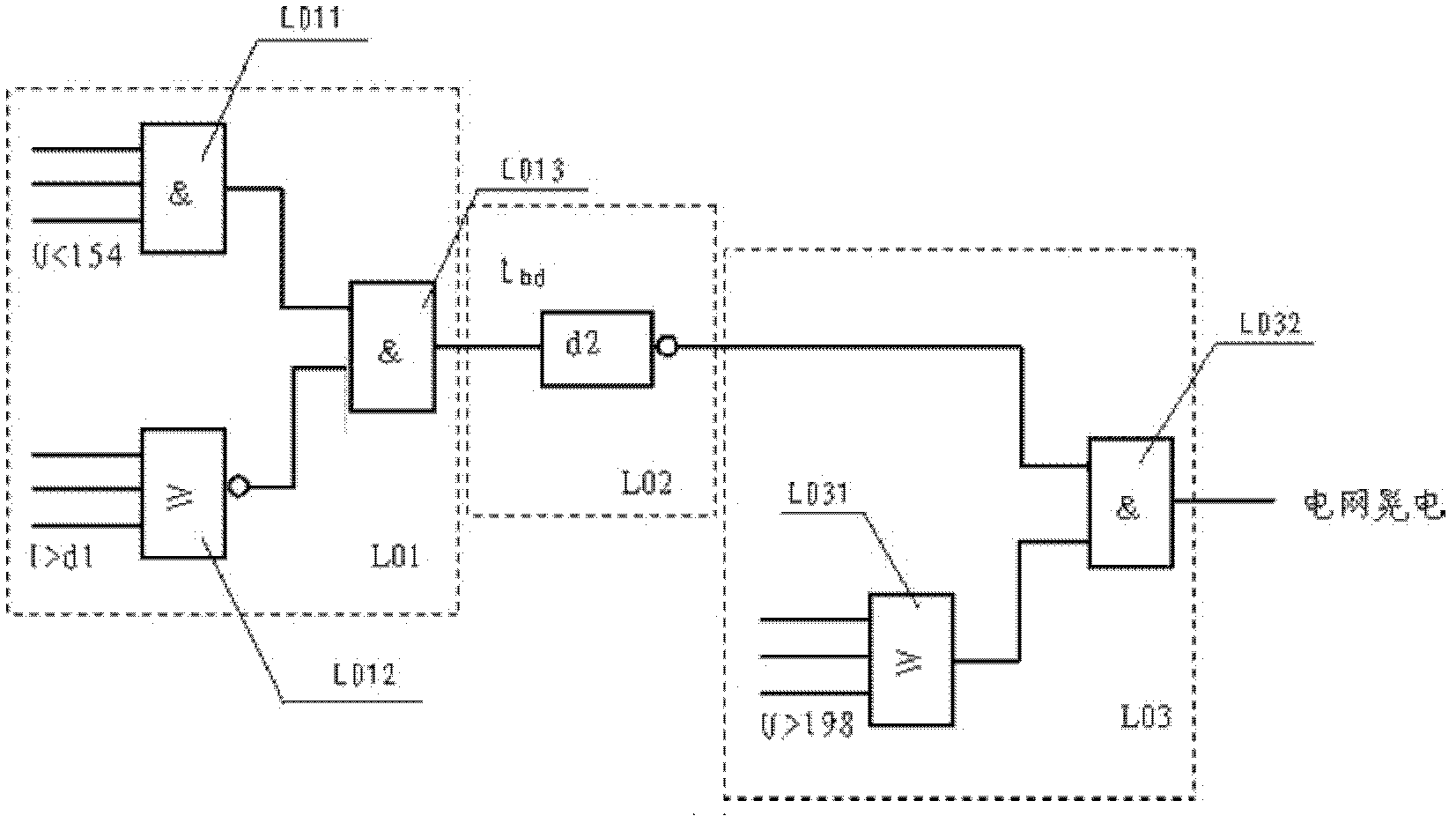
The invention relates to an anti-interference electricity protecting method and an anti-interference electricity protecting apparatus for a motor or electric equipment under an interference electricity state of a grid. The method comprises a step of judging and identifying an interference electricity fault of the grid, which is the step for a process of judging the timeout of the over-current locking under-voltage, as well as a step of charging the protecting device; and the method can transmit an interference electricity recovering restarting signal depending on a set value of the delayed starting time. The anti-interference electricity protecting apparatus comprises a hardware module which is used for implementing an anti-interference electricity protecting function and an interference electricity state judging logic function module which is used for identifying an interference electricity fault of the grid. According to the technical scheme of the grid interference electricity identifying, the over-current locking under-voltage judgment, the under-voltage timeout locking judgment and the voltage recovery judgment are adopted, to effectively distinguish the grid fault from a motor short circuit accident, a grid interference electricity fault and a grid power-loss accident as well as other faults or accident events differing in property and type, thereby avoiding error action events of the protecting device in case of the motor short circuit accident and the grid power-loss accident, and guaranteeing the equipment and the personnel security.

Description

technical field [0001] The invention relates to the field of power electronics, in particular to an anti-sway protection method and an anti-sway protection device for electrical equipment such as a motor in a state of power grid sway. Background technique [0002] Sloshing electricity refers to the electrical fault phenomenon of the power grid voltage due to lightning strikes, electrical short-circuit accidents in a certain circuit in the power grid, or electrical operations. [0003] Since the sloshing process is instantaneous, and only the voltage is affected by it, most electrical equipment will not be damaged by the sloshing fault itself, but the instantaneous drop of the grid voltage will lead to AC power supply relying on the grid voltage. The contactor coil supply voltage drops momentarily. Under normal circumstances, as long as the electric fault time is longer than 60 milliseconds and the voltage value is lower than 70% of the rated voltage value, the AC contactor ...

Claims


Application Information

Patent Timeline
IPC IPC(8): H02H3/24H02H3/08H02H3/06H02H7/18
Inventor 艾德越
Owner BAOWU CHARCOAL MATERIAL TECH CO LTD
Learn More