Method for inhibiting second harmonic current of preceding-stage inverter of two-stage inverter and control circuit of preceding-stage inverter of two-stage inverter

A control circuit and inverter technology, which is applied to electrical components, output power conversion devices, etc., can solve the problem of intermediate bus voltage drop and overshoot, low cut-off frequency of the front-stage DC converter voltage outer loop, and inverter output Voltage clipping and other issues

Inactive Publication Date: 2012-12-26
NANJING UNIV OF AERONAUTICS & ASTRONAUTICS
View PDF3 Cites 16 Cited by
  • Summary
  • Abstract
  • Description
  • Claims
  • Application Information

AI Technical Summary

Problems solved by technology

However, this method makes the cut-off frequency of the front-stage DC converter voltage outer loop lower, resulting in poor dynamic characteristics. When the load changes suddenly, the intermediate bus voltage will drop and overshoot obviously.
The obvious drop of the bus voltage may cause the output voltage of the inverter to "cut the top", thus affecting the power supply quality of the load in the dynamic process, and the obvious overshoot of the bus voltage will greatly increase the voltage of the switching tube of the subsequent inverter stress

Method used


Image

  • Method for inhibiting second harmonic current of preceding-stage inverter of two-stage inverter and control circuit of preceding-stage inverter of two-stage inverter
  • Method for inhibiting second harmonic current of preceding-stage inverter of two-stage inverter and control circuit of preceding-stage inverter of two-stage inverter
  • Method for inhibiting second harmonic current of preceding-stage inverter of two-stage inverter and control circuit of preceding-stage inverter of two-stage inverter

Examples


Embodiment Construction

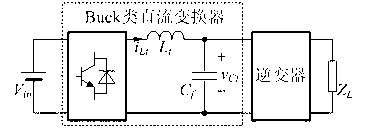
[0025] attached figure 1 The structural block diagram of the two-stage inverter is given, which is composed of a Buck DC converter in the front stage and a cascaded inverter in the rear stage. Since the instantaneous output power of the rear-stage inverter contains pulsating power of twice the frequency of the output voltage, there is a second harmonic current of twice the frequency of the output voltage in the front-stage DC converter. The present invention proposes a second harmonic current suppression method based on the current inner loop of the band-pass filter for the front-stage Buck DC converter.

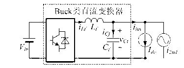
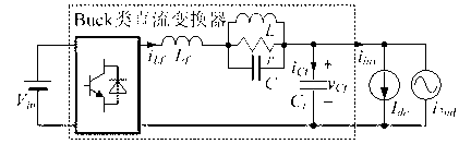
[0026] attached figure 2 The circuit schematic diagram of the simplified two-stage inverter is given. It can be seen from the figure that the second harmonic current at the input end of the inverter is shared by the inductance branch and the capacitance branch. In order to reduce the second harmonic current in the filter inductance branch, it is necessary to change the b...


PUM


Abstract

The invention relates to a method for inhibiting second harmonic current of a preceding-stage inverter of a two-stage inverter and a control circuit of the preceding-stage inverter of the two-stage inverter. By the method, the low-frequency pulse current of the preceding-stage direct current inverter can be inhibited obviously, the dynamic performance can be improved and the dynamic response speed is increased. The control circuit of the preceding-stage inverter consists of a band-pass filter, a voltage regulator, a summator, a power-width modulation (PWM) modulator and a driving circuit. The work principle is as follows: a voltage sampling circuit detects intermediate bus voltage, compares the intermediate bus voltage with a voltage reference signal to generate an error signal and transmits the error signal to the voltage regulator; a current sampling circuit detects the inductive current of the preceding-stage direct current inverter; the inductive current of the preceding-stage direct current inverter, an output signal of band-pass filter and an output signal of the voltage regulator are added by the summator to generate a modulation signal; the modulation signal is transmitted to a PWM modulation circuit; and a driving signal of a switch tube is acquired by the driving circuit, so that operation of the preceding-stage direct current inverter is controlled.

Description

technical field [0001] The invention relates to a method for suppressing low-frequency pulsating current of a front-stage converter in a two-stage inverter and a control circuit thereof, belonging to the category of new energy generation and power electronic conversion. Background technique [0002] With the increasingly serious energy crisis and environmental pollution, the development and utilization of new energy sources are paid more and more attention by people. At present, the main way of development and utilization of new energy is distributed power generation, of which the inverter is an important component core. According to the number of stages of the inverter, it can be divided into two categories: single-stage and two-stage. Due to the gap and randomness of the new energy power supply unit, the input voltage range of the inverter is often wide. The two-stage inverter can use the front-stage DC converter to regulate voltage, which is beneficial to the optimal de...

Claims


Application Information

Patent Timeline
Patent Type & Authority Applications(China)
IPC IPC(8): H02M1/14
Inventor 张力任小永阮新波
Owner NANJING UNIV OF AERONAUTICS & ASTRONAUTICS
Why Eureka
Try Eureka