
Switch magnetic resistance motor controller based on synchronous rectification technology

A switched reluctance motor and synchronous rectification technology, applied in the direction of AC motor control, electronic commutation motor control, control system, etc., to achieve the effect of easy implementation, improved stability and reliability, simple and practical circuit principle and structure

Inactive Publication Date: 2012-12-26
SOUTHEAST UNIV
View PDF5 Cites 2 Cited by
  • Summary
  • Abstract
  • Description
  • Claims
  • Application Information

AI Technical Summary

Problems solved by technology

However, there is no such application in the switched reluctance motor, which is mainly due to the special structure of the switched reluctance motor.

Method used


Image

  • Switch magnetic resistance motor controller based on synchronous rectification technology
  • Switch magnetic resistance motor controller based on synchronous rectification technology
  • Switch magnetic resistance motor controller based on synchronous rectification technology

Examples


Embodiment Construction

[0019] Below in conjunction with accompanying drawing and specific embodiment, further illustrate the present invention, should be understood that these embodiments are only for illustrating the present invention and are not intended to limit the scope of the present invention, after having read the present invention, those skilled in the art will understand various aspects of the present invention Modifications in equivalent forms all fall within the scope defined by the appended claims of this application.

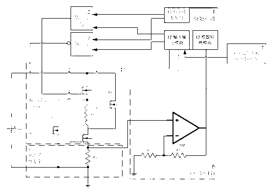
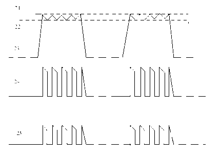
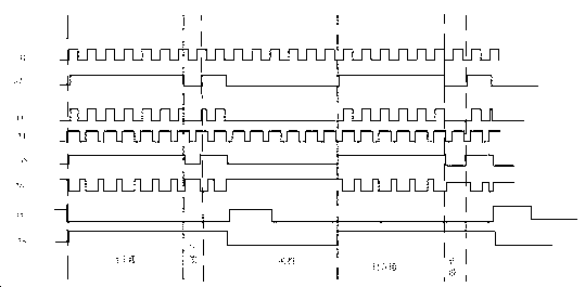
[0020] Such as figure 1 As shown, the present invention includes a microprocessor 1 , a first AND gate 2 , a first NAND gate 3 , a current sampling circuit 5 , a sampling amplifier circuit 6 , a reluctance motor position sensor 7 and a power converter 4 . The microprocessor 1 adopts a 32-bit single-chip microcomputer, which includes a pulse width modulation module 11 , an input and output module 12 and an analog-to-digital conversion module 13 . The pulse width modulati...


PUM


Abstract

The invention discloses a switch magnetic resistance motor controller based on a synchronous rectification technology. The controller comprises a microprocessor, a first and gate, a first nand gate, a current sampling circuit, a sample amplification circuit, a magnetic resistance motor position sensor and a power transformer. In a motor operating stage, the microprocessor determines a currently switch-on phase by analyzing a signal from the switch magnetic resistance motor position sensor, and simultaneously determines the current state of the current according to the sample amplification signal of the sample amplification circuit. The microprocessor controls an upper and a lower follow current MOS (Metal oxide semiconductor) tube in the power transformer according to the state of the switch magnetic resistance motor position and the state of the current. The controller disclosed by the invention can utilize a MOS tube groove to provide a follow current channel in a switch magnetic resistance motor winding and follow current stage, and generates smaller switch-on loss than existing diode follow current technology, thus energy loss and power transformer temperature rise are reduced, the system is more reliable and safer, follow current tube low temperature effect is achieved, and the reliability and safety of the system are improved.

Description

technical field [0001] The invention relates to a switched reluctance motor controller based on synchronous rectification technology, which belongs to the field of motor control. Background technique [0002] The switched reluctance motor has simple and firm structure, reliable operation and high efficiency. Compared with the traditional AC and DC speed control system, the switched reluctance motor drive system composed of it has many advantages, such as: large starting torque, wide speed range, Flexible control, convenient to realize four-quadrant operation, strong regenerative braking ability, high efficiency in a wide range of speed and power, which is conducive to energy saving and consumption reduction; it can work at extremely high speed; it can run in open phase, Strong fault tolerance, etc. [0003] Compared with other DC motors, the working current of the switched reluctance motor is large. The traditional scheme of using diodes for freewheeling due to the large fo...

Claims


Application Information

Patent Timeline
Patent Type & Authority Applications(China)
IPC IPC(8): H02P6/00H02P25/092
Inventor 钟锐赵荣渟陈磊钱钦松孙伟锋陆生礼时龙兴
Owner SOUTHEAST UNIV
Learn More