Internal combustion engine with two fluid-tightly separated lubrication spaces

A technology of internal combustion engine and space, applied in the direction of lubrication of valve accessories, lubricating parts, lubricant conduit device, etc., can solve the problem that the lubrication of diesel internal combustion engine is not completely solved, and achieve the effect of avoiding long-term wear and shortening heat resistance

Inactive Publication Date: 2016-01-13
SCHAEFFLER TECH AG & CO KG
View PDF16 Cites 0 Cited by
  • Summary
  • Abstract
  • Description
  • Claims
  • Application Information

AI Technical Summary

Problems solved by technology

The solution pointed out in DE3029964C2 for the method for lubricating diesel internal combustion engines does not fully solve this problem

Method used


Image

  • Internal combustion engine with two fluid-tightly separated lubrication spaces
  • Internal combustion engine with two fluid-tightly separated lubrication spaces

Examples


Embodiment Construction

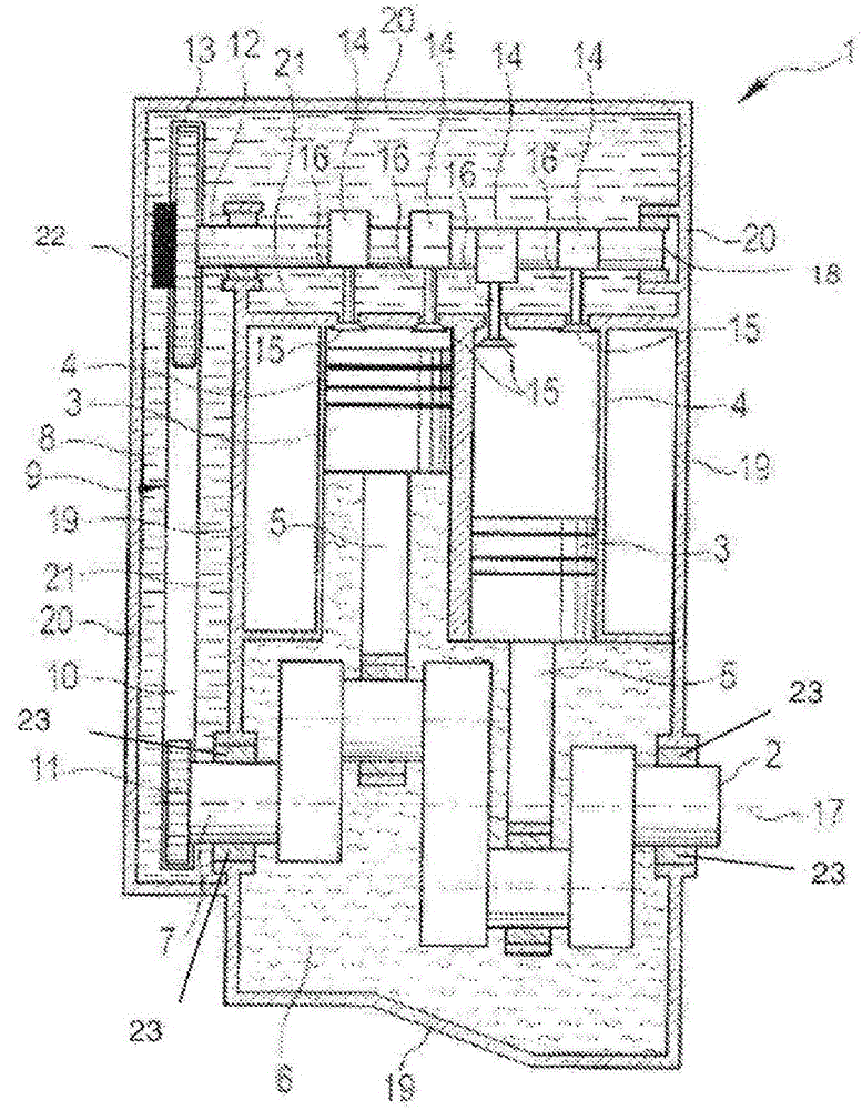
[0032] figure 1 The illustration of the internal combustion engine 1 is only schematic in nature and serves only for the understanding of the invention.

[0033] Internal combustion engine 1 has a crankshaft 2 , which is driven by two pistons 3 here by way of example. exist figure 1 The two pistons 3 shown in are arranged linearly movable in two cylinders 4 . Not shown, the cylinder 4 also includes a cylinder sleeve. The movement of the piston 3 is transmitted to the crankshaft 2 via the connecting rod 5 . Only sufficiently known connecting rod bearings are shown.

[0034] Also only the bearings of the crankshaft 2 are shown.

[0035] The crankshaft 2 is mainly arranged in the first space 6 . Only a small end section 7 of the crankshaft 2 protrudes from the first space 6 into the second space 8 . A synchronous transmission 9 is also provided in the second space 8 . The synchronous transmission 9 includes a traction mechanism 10 which is in operative contact with a gear...


PUM


Abstract

Internal combustion engine (1) with: a crankshaft (2), at least one camshaft (12) for operating gas exchange valves (15, 104), and a synchronous transmission (9) which connects the crankshaft (2) The rotation of the crankshaft (12) is transmitted to the camshaft (12), wherein the crankshaft (2) is mainly arranged in the first space (6), which is fluidly connected with the second space (8) in which the synchronous transmission (9) is arranged. densely separated, wherein a camshaft (12) is also arranged in the second space (8).

Description

technical field [0001] The invention relates to an internal combustion engine with a crankshaft, at least one camshaft for actuating gas exchange valves and a synchronous transmission which transmits the rotation of the crankshaft to the camshaft, wherein the crankshaft is mainly arranged in a first space , the first space is fluid-tightly separated from the second space in which the synchronous transmission is arranged. Background technique [0002] Internal combustion engines are used to provide a power source in motor vehicles, such as passenger cars, trucks, or other land vehicles. However, such internal combustion engines are also used in vehicles that travel in water or on land. [0003] Internal combustion engines typically have one or more cylinders in which pistons are reciprocated as a result of the explosive combustion of a fuel, for example diesel fuel or gasoline fuel. Movement of one or more connecting rods induced by burning fuel is transmitted to at least o...

Claims


Application Information

Patent Timeline
Patent Type & Authority Patents(China)
IPC IPC(8): F01L1/02F01L9/02F01M9/10F02B75/20F01L9/14
CPCF01L1/022F01L1/024F01L2001/34446F01L2810/02F01M9/10F01M11/02F01L1/02F01L9/14F02B75/20
Inventor 博尔科·舒塞伊拉约什·法尔卡斯克劳斯·哈恩
Owner SCHAEFFLER TECH AG & CO KG
Why Eureka
Try Eureka