Flotation column

A flotation column and column technology, applied in flotation, solid separation, etc., can solve the problems that the gas cannot be uniformly dispersed, difficult to check and maintain, and affect the strength of the flotation column, so as to achieve easy inspection and maintenance, long service life, The effect of stable performance

Active Publication Date: 2013-01-02
BGRIMM MACHINERY & AUTOMATION TECH CO LTD +1
View PDF7 Cites 3 Cited by
  • Summary
  • Abstract
  • Description
  • Claims
  • Application Information

AI Technical Summary

Problems solved by technology

First of all, the uniformity of the gas in the aerator in the flotation column will be affected by the size of the cross-section of the flotation column. If the cross-sectional area is small, the gas dispersion will be high and easy to control. The range of the ejected gas is limited so that the gas cannot be evenly dispersed on the entire cross-section of the column; secondly, the flotation column is generally 8-15m high, and a certain mechanical strength should be guaranteed in the direction of the column. Too much quantity distributed in the circumferential direction, too dense will affect the strength on the circumference of the wall of the flotation column and it will be difficult to check and maintain
The degree of gas dispersion in the flotation column directly affects the process performance of the equipment. It is necessary to ensure that the gas charged into the flotation column from the aerator can be evenly dispersed on the cross section of the column, and at the same time, the flotation column has sufficient mechanical strength and convenience. Inflator inspection and maintenance conditions, this kind of inflator configuration obviously has limitations

Method used


Image

  • Flotation column
  • Flotation column
  • Flotation column

Examples


Embodiment Construction

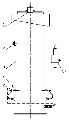
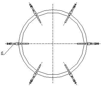
[0017] The flotation column of the present invention includes a spray water assembly, a ore supply system, a column assembly and a tailing system, and the flotation column also includes a flotation column cone bottom and a plurality of flotation column aerators (see Figure 4 ), the cone bottom 8 of the flotation column is located in the lower part of the flotation column, the cone bottom of the cone bottom 8 of the flotation column is downward in a funnel shape, and the upper edge is welded to the inner wall of the column assembly. The conical column bottom 8 of the flotation column provides ample space for the configuration of the flotation column aerator, ensuring that the aerator can be distributed in multiple circles at different heights in the space; and can promote the smooth discharge of the slurry in the flotation column to prevent Mineral particles pile up and sink.

[0018] Multiple flotation column aerators 7 are installed on the bottom of the conical column, such as ...


PUM


Abstract

The invention discloses a flotation column which comprises a spraying water component, a feeding system, a column component and a gangue system, and further comprises a taper column bottom of the flotation column and a plurality of flotation column aerators, wherein the taper column bottom of the flotation column is located on the lower part inside the flotation column; the plurality of flotation column aerators are installed on the taper column bottom; the flotation column aerators are vertically installed at different height positions of the taper column bottom of the flotation column and are distributed along a plurality of circumferences of the taper column bottom of the flotation column. The flotation column aerators are distributed on the plurality of circumferences at different height positions of the taper column bottom of the flotation column, so that the distribution quantity of the aerators in a cross section of a column body is controlled according to the needed air flow and the size of the cross section of the flotation column of a selected process, dispersion degree of gas injected in the column is high; and the flotation column aerators are longer in service lives and stable in work performance under protection of wear-resisting steel tubes.

Description

Technical field [0001] The invention relates to the field of beneficiation, in particular to a flotation column. Background technique [0002] Flotation column is a kind of beneficiation equipment, which is widely used in the separation of non-ferrous metals, ferrous metals and non-metallic minerals. See figure 1 , The flotation column is usually composed of spray water assembly 1, feeding system 2, column assembly 3, aeration system 4 and tailings system 5. When the direct air injection flotation column is working, the high-pressure air (0.5~0.7MPa) from the air compressor is sprayed into the flotation column at high speed through the inflation system installed at the bottom of the flotation column, and the slurry in the flotation column is cut. A large number of small bubbles are generated under the shearing action, and the bubbles rise slowly from the bottom of the column; the slurry is fed from the height of 2 / 3 of the column, and after being evenly distributed by the ore fe...

Claims


Application Information

Patent Timeline
IPC IPC(8): B03D1/24
Inventor 卢世杰赖茂河周宏喜谭明史帅星
Owner BGRIMM MACHINERY & AUTOMATION TECH CO LTD
Why Eureka
Try Eureka