
Face milling device

A face milling and milling technology, which is applied to positioning devices, feeding devices, milling machines, etc., can solve the problems of difficulty in meeting the size range of large box beams or H-shaped steel beams, limited processing range, and narrow working table of face milling machines. To achieve the effect of convenient inspection and maintenance, improve production efficiency, and expand the scope of processing

Inactive Publication Date: 2014-10-15
WUXI WEIHUA ELECTRIC WELDING MFG
View PDF8 Cites 0 Cited by
  • Summary
  • Abstract
  • Description
  • Claims
  • Application Information

AI Technical Summary

Problems solved by technology

[0002] The working surface of traditional face milling machines is relatively narrow, and the processing range is limited, so it is difficult to meet the size range of large box beams or H-shaped steel beams; in addition, most of the traditional face milling machines use ordinary stepping motors, which need to manually control the lifting of the milling head and movement speed

Method used


Image

  • Face milling device
  • Face milling device
  • Face milling device

Examples


Embodiment Construction

[0018] The specific embodiments of the present invention will be further described below in conjunction with the accompanying drawings.

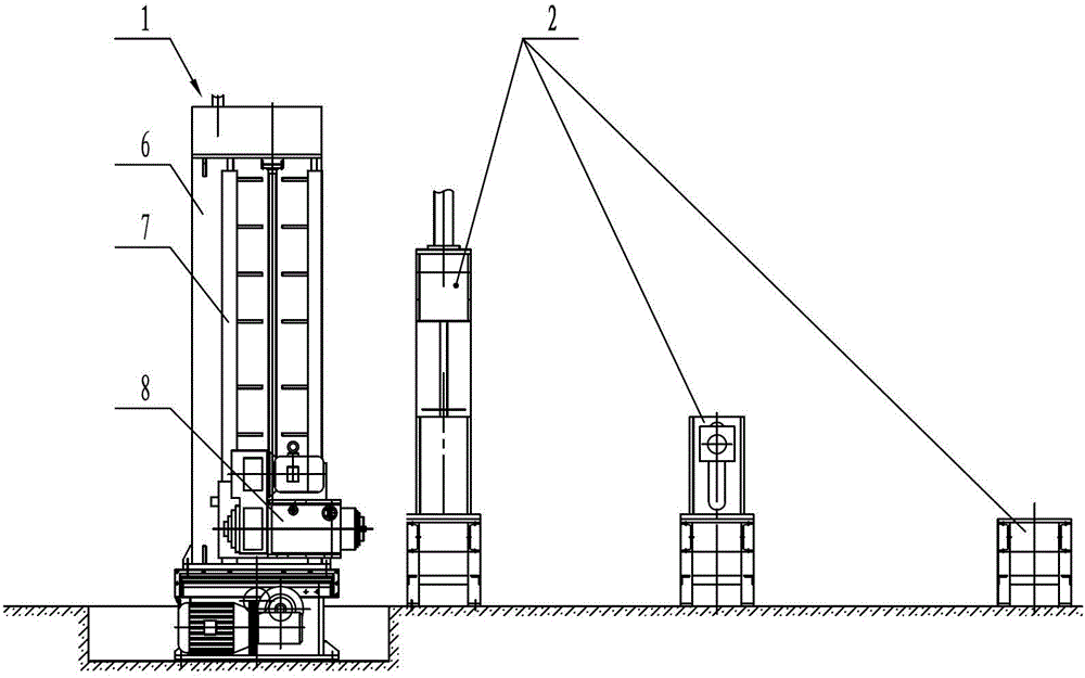
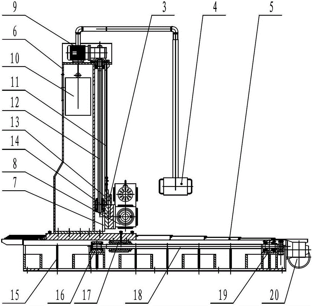
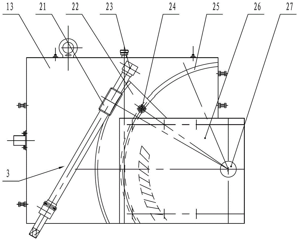
[0019] Figure 1~Figure 4 Including milling host 1, workpiece support frame 2, angle adjustment mechanism 3, operation control box 4, guide rail dustproof mechanism 5, column 6, vertical slide rail 7, milling head 8, first motor reducer 9, counterweight 10. Steel wire rope 11, vertical screw rod 12, lifting pallet 13, vertical screw nut 14, machine base 15, rear support base 16, horizontal screw nut 17, horizontal screw rod 18, front support base 19, second motor reducer 20 , Worm screw 21, worm gear 22, bearing housing 23, T-shaped bolt 24, T-shaped slot 25, milling head mount 26, mandrel 27, etc.

[0020] like figure 1 , figure 2 As shown, the present invention is a face milling device, including a milling host 1 and a workpiece support frame 2 . The milling host 1 is used to complete the cutting movement in the horizontal and vertica...


PUM


Abstract

The invention relates to an end face milling device, which comprises a milling host and a workpiece supporting frame, wherein the milling host comprises a seat, a stand column and a milling head; the seat is provided with a horizontal guide rail; the stand column is in sliding fit with the horizontal guide rail and is connected with a horizontal transmission mechanism; a vertical slide rail is arranged on the stand column and is in sliding fit with a lifting base plate; and the milling head is arranged on the lifting base plate and is connected with a vertical transmission mechanism. According to the end face milling device, the workpiece supporting frame for clamping and positioning a workpiece is additionally arranged in addition to the milling host, so that the machining range is expanded, and end face machining of a large-sized box beam or an H-shaped steel beam can be met.

Description

technical field [0001] The invention relates to metal milling equipment, in particular to a device for milling the end faces of mechanical parts. Background technique [0002] The working surface of traditional face milling machines is relatively narrow, and the processing range is limited, so it is difficult to meet the size range of large box beams or H-shaped steel beams; in addition, most of the traditional face milling machines use ordinary stepping motors, which need to manually control the lifting of the milling head and movement speed. Contents of the invention [0003] In view of the above problems, the present invention provides an end face milling device, which has a large processing range and can meet the processing of box girders or H-shaped steel girders in all sizes from large to small. [0004] According to the technical solution of the present invention: a face milling device, including a milling host and a workpiece support frame, the milling host includ...

Claims


Application Information

Patent Timeline
Patent Type & Authority Patents(China)
IPC IPC(8): B23C1/00B23Q5/40B23Q3/00B23Q11/08B23Q1/26
Inventor 彭友平吴克袁彬彬夏冬蒋爱华
Owner WUXI WEIHUA ELECTRIC WELDING MFG
Learn More