Buzzer placing mechanism

A buzzer, automatic feeding technology, used in metal processing, metal processing equipment, manufacturing tools, etc., can solve the problem of no production line, save labor, improve work efficiency and product quality, and simple structure.

Active Publication Date: 2013-01-02
CHANGZHOU MINGSEAL ROBOT TECH CO LTD
View PDF6 Cites 9 Cited by
  • Summary
  • Abstract
  • Description
  • Claims
  • Application Information

AI Technical Summary

Problems solved by technology

[0003] At present, most of the assembly and production of buzzers in China rely on manual labor and auxiliary equipment with simple procedures. There is no production line that fully realizes complex automatic assembly in China.

Method used


Image

  • Buzzer placing mechanism
  • Buzzer placing mechanism
  • Buzzer placing mechanism

Examples


Embodiment 1

[0021] This embodiment includes an automatic feeding device 1 and a handling device 2 fixed on the workbench.

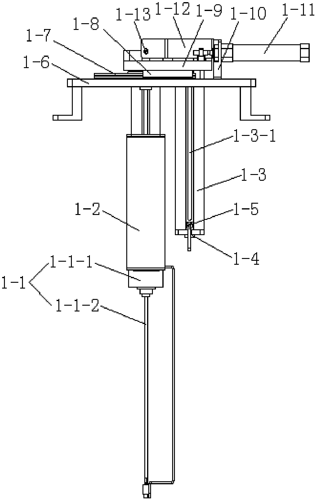
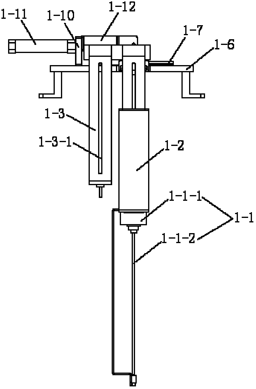
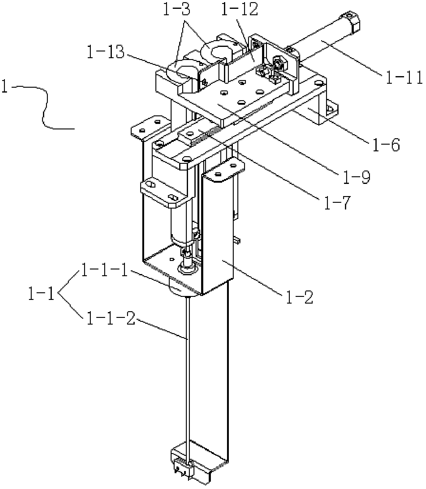
[0022] See Figure 1 to Figure 3 , the automatic feeding device 1 includes a linear stepper motor 1-1, a motor bracket 1-2, a barrel 1-3, a tray 1-4, a light sensor 1-5, a slide rail bracket 1-6, and a slide rail 1- 7. Slider 1-8, slider connecting plate 1-9, cylinder supporting plate 1-10, horizontal transposition cylinder 1-11, optical fiber sensor supporting plate 1-12 and reflective optical fiber sensor 1-13. The linear stepping motor 1-1 comprises a motor body 1-1-1 and a motor screw mandrel 1-1-2, the motor body 1-1-1 is fixed on the motor bracket 1-2, and the motor body 1-1-1 drives the motor The screw mandrel 1-1-2 moves up and down. The motor support 1-2 and the slide rail support 1-6 are respectively fixed on the lower end surface and the upper end surface of the workbench. The slide rail 1-7 is fixed on the slide rail support 1-6, the slide block 1-8 is...


PUM


Abstract

The invention discloses a buzzer placing mechanism. The buzzer placing mechanism comprises an automatic feeding device and a carrying device which are fixed on a working table; a buzzer is placed on the automatic feeding device; and the carrying device absorbs the buzzer and places the buzzer in a buzzer housing. The buzzer is placed on the automatic feeding device, and the carrying device absorbs the buzzer and places the buzzer in the buzzer housing, so that the buzzer is automatically fed and placed; and the buzzer placing mechanism can be a part of an automatic buzzer assembly production line, thereby saving labor and improving working efficiency and product quality.

Description

technical field [0001] The invention relates to a buzzer chip placement mechanism for automatically placing buzzer chips for a buzzer shell on a buzzer automatic assembly production line. Background technique [0002] The buzzer is an electronic sounder with an integrated structure. It is powered by DC voltage and is widely used as a sounding device in electronic products such as computers, printers, copiers, alarms, electronic toys, automotive electronic equipment, telephones, and timers. . [0003] At present, most of the assembly and production of buzzers in China rely on manual labor and auxiliary equipment with simple processes, and there is no production line that fully realizes complex automatic assembly in China. When the buzzer is assembled, the buzzer piece needs to be placed in the glue-coated shell. Therefore, if the production line for complex and automatic assembly of the buzzer is to be realized, the buzzer piece placement mechanism will be an indispensable p...

Claims


Application Information

Patent Timeline
Patent Type & Authority Applications(China)
IPC IPC(8): B23P19/04
Inventor 徐庆海李长峰曲东升
Owner CHANGZHOU MINGSEAL ROBOT TECH CO LTD
Why Eureka
Try Eureka