

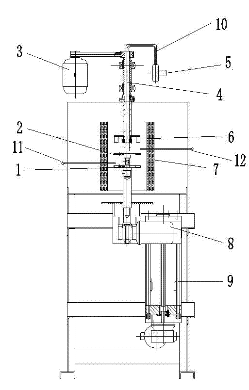
Optical glass rapid quenching furnace
A technology of optical glass and quenching furnace, which is applied in the field of optical glass quenching, to achieve the effect of improving the uniformity of temperature field, shortening the quenching cycle, and uniform temperature field
- Summary
- Abstract
- Description
- Claims
- Application Information
AI Technical Summary
Problems solved by technology
Method used
Image

Examples
Embodiment 1
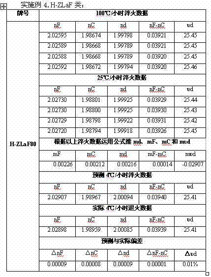
[0019] Example 1. H-ZK class:
[0020]
[0021]
[0022]
[0023]
[0024]
[0025] Note: nF, nC, nd, nF-nC, υ d represent respectively: the refractive index of the hydrogen blue line F, the refractive index of the hydrogen red line C, the refractive index of the helium yellow line d, the central dispersion, and the dispersion coefficient (that is, the Abbe number);
[0026] mF, mC, md, mF-mC, mυd Respectively: the refractive index annealing constant of the hydrogen blue line F, the refractive index annealing constant of the hydrogen red line C, the refractive index annealing constant of the helium yellow line d, the annealing constant of the middle dispersion, and the annealing constant of the dispersion coefficient (that is, the Abbe number);
[0027] △nF, △nC, △nd, △nF-nC, △υd Respectively: the difference in refractive index of the hydrogen blue line F, the refractive index difference of the hydrogen red line C, and the helium yellow line d in the case o...
PUM
 Abstract
Description
Claims
Application Information