Check drain valve of heat accumulator

A heat accumulator and drain valve technology, applied in valve details, valve device, valve operation/release device, etc., can solve the problems of air leakage, seal failure, waste heat recovery device failure in the drainage system, etc., and reduce the density of spheres , The effect of reliable sealing and simple structure

Inactive Publication Date: 2013-01-02
YANGZHOU GOLDSTAR TECH IND
View PDF6 Cites 4 Cited by
  • Summary
  • Abstract
  • Description
  • Claims
  • Application Information

AI Technical Summary

Problems solved by technology

All kinds of waste heat recovery heat exchangers are in the gas state. If they cannot reach the liquid state, severe dew point corrosion will occur, resulting in the failure of the waste heat recovery device. Regenerative transcritical flue gas waste heat recovery equipment (patent number: 200910028403.6) , The drainage of the regenerative

Method used


Image

  • Check drain valve of heat accumulator
  • Check drain valve of heat accumulator

Examples


Embodiment Construction

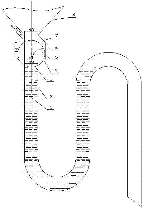
[0018] Such as figure 1 , 2 As shown, the upper and lower ends of the straight section sealing cylinder 6 are respectively sealed and connected with the upper cone section 7 and the lower cone section 4, and a floating ball 5 is arranged inside the straight section sealing cylinder 6. quality seal.

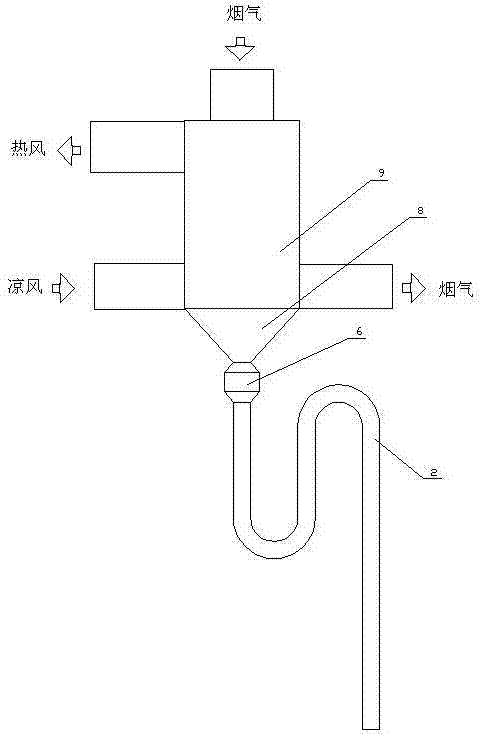
[0019] The upper end of the upper cone section 7 is provided with a liquid collecting cone 8 for connecting the heat accumulator 9 , and the lower cone section 4 is provided with a connection end for connecting the rotary liquid-sealed pipe 2 .

[0020] The height of the straight section sealing cylinder 6 is h 1 , the radius of the floating ball is d 2 , the diameter of the upper end of the upper cone section 7 and the diameter of the lower end of the lower cone section 4 are respectively d 3 , they satisfy the following conditions:

[0021] d 3 2 1 ;2d 2 ≥ h 1 ≥1.5d 2 ;d 1 2 = d 2 2 + d 3 2 .

[0022] Moreover, the inner cone angle of the upper cone section 7 is...


PUM


Abstract

The invention discloses a check drain valve of a heat accumulator, relating to the technical field of waste heat recovery of flue gas of an industrial kiln. The check drain valve comprises a sealing cylinder, wherein the top and the bottom of the sealing cylinder are provided with a taper cavity respectively; a floating ball is arranged in the sealing cylinder; the upper end of the sealing cylinder is provided with a liquid collection cone for connecting the heat accumulator; and the lower end of the sealing cylinder is provided with a connecting end for connecting a rotary liquid sealing pipe. The liquid collection cone at the upper end of the check drain valve is connected with flue gas waste heat recovery equipment, and the lower end of the check drain valve is connected with the rotary liquid sealing pipe; since liquid is filled in the rotary liquid sealing pipe in use, liquid also exists in the sealing cylinder communicated with the rotary liquid sealing pipe; and under the action of the floating ball, no phenomenon of air leakage of a drainage system is guaranteed.

Description

technical field [0001] The invention belongs to the technical field of energy saving of industrial furnaces and kilns, and in particular relates to the technical field of waste heat recovery of flue gas of industrial furnaces and kilns. Background technique [0002] There are steel pipe type, finned tube type, top tube type, heat pipe type, plate type and other forms of recovery of waste heat from combustion flue gas in industrial furnaces. All kinds of waste heat recovery heat exchangers are in the gas state. If they cannot reach the liquid state, severe dew point corrosion will occur, resulting in the failure of the waste heat recovery device. Regenerative transcritical flue gas waste heat recovery equipment (patent number: 200910028403.6) , The drainage of the regenerative heat extractor (patent number: 200910028334.9) adopts a rotary liquid-sealed non-return structure. In engineering practice, the seal will fail due to the suction force of the chimney or the pressure flu...

Claims


Application Information

Patent Timeline
IPC IPC(8): F16K31/18
Inventor 葛京鹏胡秀高张勇
Owner YANGZHOU GOLDSTAR TECH IND
Why Eureka
Try Eureka