Method and device for controlling pressure in fire-resistance rating test furnace

A technology of refractory limit and control device, which is applied to furnace control device, furnace, furnace type, etc., can solve the problems of control, no test furnace pressure is proposed, and achieve the effect of uniform pressure distribution control and reducing direct influence.

Active Publication Date: 2013-01-02
广州市建筑材料工业研究所有限公司
View PDF7 Cites 6 Cited by
  • Summary
  • Abstract
  • Description
  • Claims
  • Application Information

AI Technical Summary

Problems solved by technology

But this utility model also does not propose a kind of specific method that the pressure in the test furnace is controlled

Method used


Image

  • Method and device for controlling pressure in fire-resistance rating test furnace

Examples


Embodiment 1

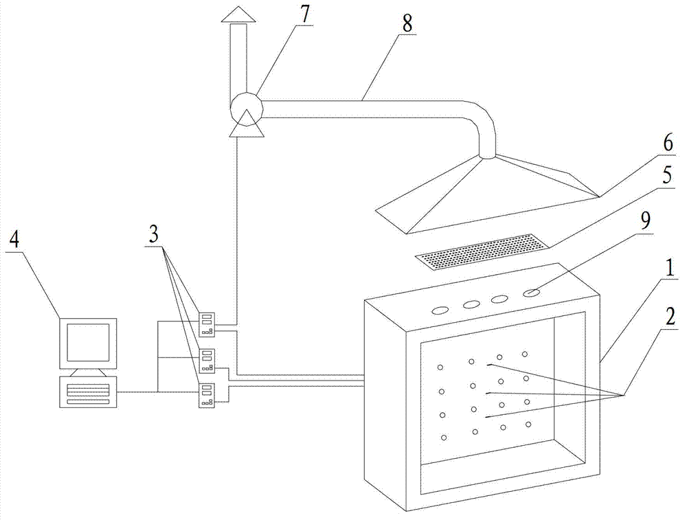
[0029] Such as figure 1 As shown, in this embodiment, a pressure control device in a fire resistance limit test furnace includes a fire resistance limit test furnace 1 for exhausting smoke at the top, a pressure sensor 2 in the furnace, a PID controller 3, a computer 4, a smoke collecting hood 6, and a smoke exhaust fan 7. The smoke exhaust pipe 8 and the porous smoke exhaust steady flow net 5, the pressure sensor 2 in the furnace is set in the fire resistance limit test furnace 1, connected with the PID controller 3, and used to transmit the actual pressure data in the furnace to the PID controller 3 . The computer 4 is connected with the PID controller 3 for transmitting the target pressure data to the PID controller 3 . The PID controller 3 is used to compare and analyze the actual furnace pressure data and the target pressure data, and then control the speed of the exhaust fan 7 according to the analysis results. The porous smoke exhaust stabilizing net 5 is covered on t...

Embodiment 2

[0040] Present embodiment except following feature other structures are with embodiment 1:

[0041] In this embodiment, the number of pressure sensor 2 in the furnace is one, and the output type of the pressure sensor is 0~5V. The number of the PID controller 3 is one, and the PID controller 3 is connected with the computer 4 , the pressure sensor 2 and the exhaust fan 7 respectively.

[0042] The smoke exhaust hole 9 on the top of the test furnace is located at the top of the test furnace 1, the number of smoke exhaust holes 9 is 2, and the cross-sectional area of ​​a single smoke exhaust hole is 0.5m 2 .

[0043] The porous smoke exhaust and flow stabilization net 5 is a porous plate made of high temperature resistant ceramics, the thickness of the plate is 15mm, the through-hole ratio of the plate is 30%, and the diameter of the hole is 20mm. The perforated plate is directly covered on the smoke exhaust hole 9, and the quantity of the porous plate can be 2, each covering ...

Embodiment 3

[0046] Present embodiment except following feature other structures are with embodiment 1:

[0047] In this embodiment, the number of pressure sensors 2 in the furnace is five, and the output type of the pressure sensors is 4-20 mA. The number of PID controllers 3 is five, and each PID controller 3 is connected with the computer 4 and the pressure sensor 2 respectively, and one of them is also connected with the exhaust fan 7 .

[0048] In the present embodiment, the number of smoke exhaust holes 9 is 10, and the cross-sectional area of ​​a single smoke exhaust hole is 0.1m 2 . The porous smoke exhaust stabilization net 5 is a porous plate made of high temperature resistant ceramics, the thickness of the plate is 100mm, the through-porosity of the plate is 50%, and the diameter of the hole is 10mm. The number of perforated plates is 10, and one smoke exhaust hole is covered at the same time.

[0049] The height of the gap between the bottom four sides of the fume collecting...


PUM


Abstract

The invention discloses a method and a device for controlling the pressure in a fire-resistance rating test furnace. The device comprises the fire-resistance rating test furnace, pressure sensors, PID (proportion integration differentiation) controllers, a computer, porous smoke-discharge flow stabilization nets, a smoke collecting hood, a smoke discharge fan and a smoke discharge pipeline. According to the method, when fuel in the fire-resistance rating test furnace begins to burn, the pressure sensors in the furnace and the computer are used for sending actual in-furnace pressure data and set target pressure data to the PID controllers respectively, the PID controller is used for making comparison and analysis on the data and then sending a control instruction to the smoke discharge fan so that the rotation speed of the fan is regulated, and under the action of the smoke discharge fan, the smoke passes the test furnace, flows out of smoke discharge holes arranged at the top of the test surface, then passes the porous smoke-discharge flow stabilization nets into the smoke collecting hood and is discharged by the smoke discharge fan to a smoke treatment system. The method and the device adopt the computer and the PID controllers to control the pressure in the test furnace by changing the rotation speed of the smoke discharge fan, so that the pressure distribution in the test furnace can be controlled uniformly and stably.

Description

technical field [0001] The invention relates to the design field of a fire resistance limit test furnace, in particular to a method and device for controlling the pressure in a fire resistance limit test furnace. Background technique [0002] The fire resistance test is a test method to detect the fire resistance of building components by simulating a real fire. The building components based on this test include walls, ceilings, floors, beams, columns, fire doors, fire shutters, fire windows, fire protection Fireproof coatings for glass and steel structures, fireproof sealing materials, smoke exhaust valves, fire dampers, etc. Through the fire resistance limit test, the fire resistance performance of the tested parts can be correctly judged, so as to provide guiding data for building design and acceptance, thereby improving the fire safety of buildings. [0003] The fire resistance test must simulate a real fire. During the test, the temperature in the test furnace must mee...

Claims


Application Information

Patent Timeline
Patent Type & Authority Applications(China)
IPC IPC(8): F27B17/02F27D19/00
Inventor 刘建勇凌翩杨展林玩君赵侠吴欣余稳松邬玉龙易爱华
Owner 广州市建筑材料工业研究所有限公司
Why Eureka
Try Eureka