Light guide plate and preparation and application thereof
A light guide plate and light source technology, which is applied in the field of light guide plate and its preparation and application, can solve problems such as the triangular dark area of the light guide plate, Hotspot phenomenon, etc., achieve the effect of increasing density, solving the Hotspot problem, and meeting the demand for uniform light mixing
- Summary
- Abstract
- Description
- Claims
- Application Information
AI Technical Summary
Problems solved by technology
Method used
Image
Examples
Embodiment 1
[0052] The light guide plate of this embodiment includes low-density regions and high-density regions. The low-density area uses PMMA material, the high-density area uses PC material, and the two areas use different gates. Since the material is in a liquid state during injection molding and the temperature is very high, the two materials are easily combined in a liquid state.
[0053] In this embodiment, an injection molding method is used to prepare a light guide plate.
[0054] In this embodiment, two injection molding machines are used to complete the injection molding by transferring the mould.
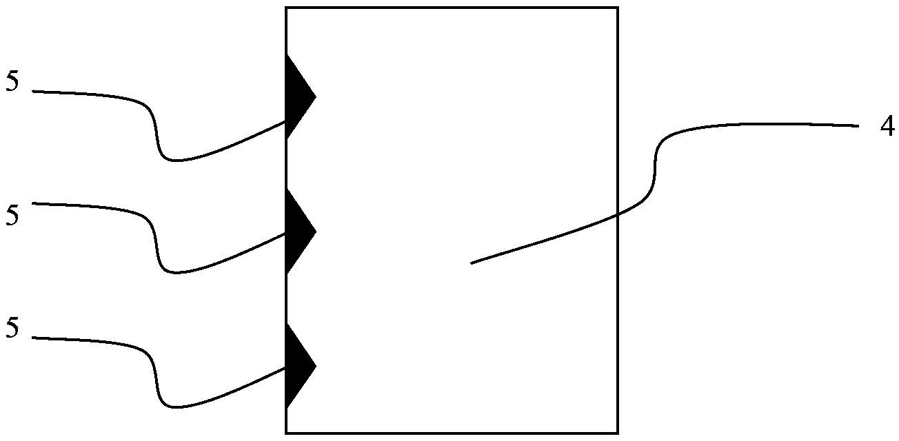
[0055] refer to Figure 4 , the high-density area 5 is the PC material injection molding area, and the low-density area 4 is set as the core-pulling mold.
[0056] First, inject high-density PC material into the first injection molding machine to form a semi-molded module;
[0057] Then, transfer the semi-formed module to the injection position of the second injection molding ...
Embodiment 2
[0074] The light guide plate of this embodiment includes low-density regions and high-density regions. The low-density area uses PMMA material, the high-density area uses PC material, and the two areas use different gates. Since the injection molding material is liquid and the temperature is very high, the two materials are easily combined in the liquid state.
[0075] In this embodiment, an injection molding method is used to prepare a light guide plate.
[0076] refer to Figure 4 , the high-density area 5 is the PC material injection molding area, and the low-density area 4 is set as the core-pulling mold.
[0077] First, inject high-density PC material into the injection molding machine to form a semi-molded module;
[0078] Then, the mold is rotated 180°, the core-pulling mold is drawn out, the pouring port of the low-density material PMMA is aligned with the pouring port of the PC, and PMMA is poured, thereby completing the injection molding of the semi-finished light...
Embodiment 3
[0094] Example 3: Comparison of high-density areas in different ranges for improving triangular dark areas
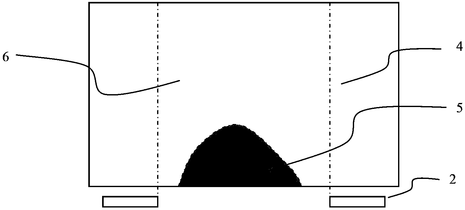
[0095] When the side light sources used are several independent LED light sources, by adjusting the range of the high-density area in the area between two adjacent independent LED light sources, the inventor found that when the high-density area just occupies two adjacent independent LED light sources When the triangular dark area is small, the improvement effect on the triangular dark area is the best, and there is no loss to the light efficiency of the LED.
PUM
| Property | Measurement | Unit |
|---|---|---|
| density | aaaaa | aaaaa |
| melting point | aaaaa | aaaaa |
| melting point | aaaaa | aaaaa |
Abstract
Description
Claims
Application Information
 - R&D
- Intellectual Property
- Life Sciences
- Materials
- Tech Scout
- Unparalleled Data Quality
- Higher Quality Content
- 60% Fewer Hallucinations
Browse by: Latest US Patents, China's latest patents, Technical Efficacy Thesaurus, Application Domain, Technology Topic, Popular Technical Reports.
© 2025 PatSnap. All rights reserved.Legal|Privacy policy|Modern Slavery Act Transparency Statement|Sitemap|About US| Contact US: help@patsnap.com


