Laser light source collimating device, collimating device array, lighting system and projection equipment

A laser light source and lighting system technology, applied in the field of optics, can solve the problems of difficult to guarantee machining accuracy and difficult processing of a collimating device, and achieve the effects of good collimation, easy guarantee of machining accuracy, and convenient machining.

Inactive Publication Date: 2013-01-02
WUHU AMT MICRO DISPLAY TECH
View PDF2 Cites 12 Cited by
  • Summary
  • Abstract
  • Description
  • Claims
  • Application Information

AI Technical Summary

Problems solved by technology

[0004] The purpose of the present invention is to provide a laser light source collimation device, aiming to solve the problems of the existing collimation devices that are difficult to process and difficult to guarantee the processing accuracy, and at the same time further improve the collimation effect of the laser

Method used


Image

  • Laser light source collimating device, collimating device array, lighting system and projection equipment
  • Laser light source collimating device, collimating device array, lighting system and projection equipment
  • Laser light source collimating device, collimating device array, lighting system and projection equipment

Examples


Embodiment Construction

[0025] In order to make the object, technical solution and advantages of the present invention clearer, the present invention will be further described in detail below in conjunction with the accompanying drawings and embodiments. It should be understood that the specific embodiments described here are only used to explain the present invention, not to limit the present invention.

[0026] The specific realization of the present invention is described in detail below in conjunction with specific embodiment:

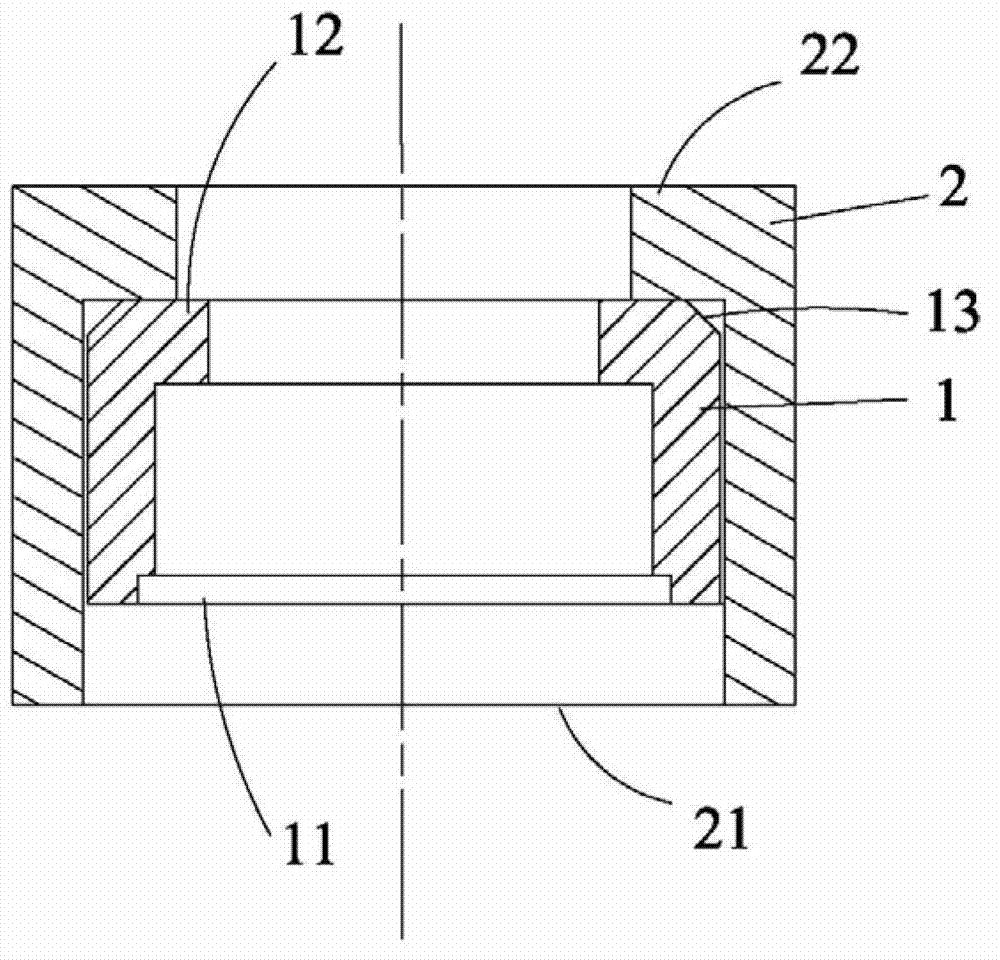
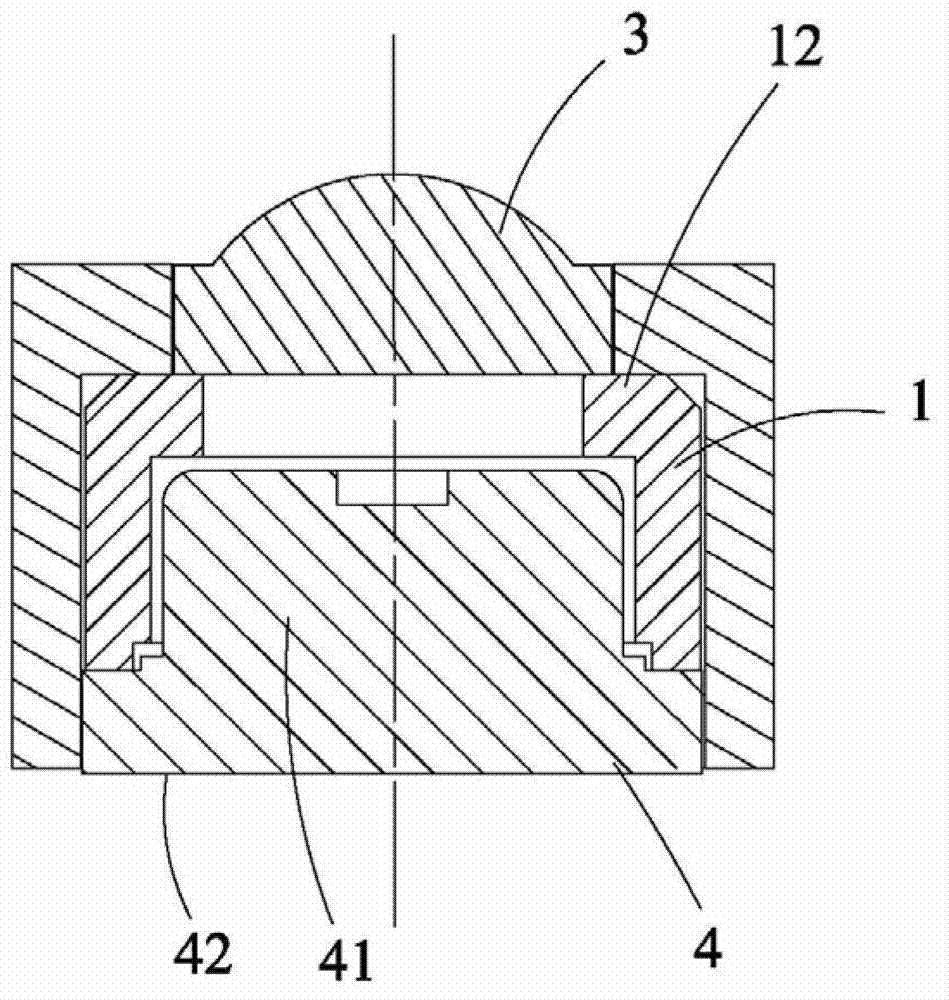
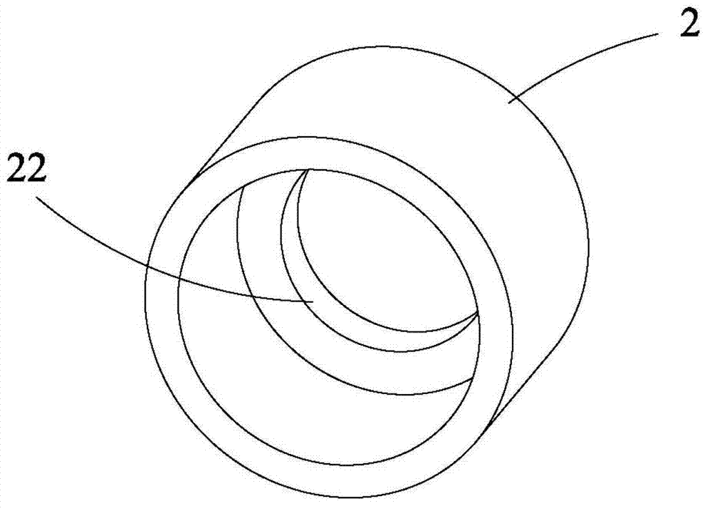
[0027] figure 1 shows a cross-sectional view of the laser light source collimation device provided by the embodiment of the present invention, figure 2 Shows the sectional view of the laser light source collimating device assembled with the laser and collimating lens, image 3 , 4 A perspective view and a half-sectional view of the outer sleeve are shown respectively, Figure 5 , 6 A perspective view and a half-sectional view of the inner sleeve are shown respective...


PUM


Abstract

The invention is suitable for the technical filed of optics and provides a laser light source collimating device, a collimating device array, a lighting system and projection equipment. The collimating device comprises an inner sleeve and an outer sleeve, wherein both ends of the inner sleeve are located in the outer sleeve; one end of the outer sleeve is provided with a first opening and the other end of the outer sleeve is provided with a first flange extending inwards; the center axes of the first flange and the first opening are overlapped; one end (close to the first opening) of the inner sleeve is provided with a second opening and the other end of the inner sleeve is provided with a second flange extending inwards; and the upper surface of the second flange presses against the lower surface of the first flange and the second flange is bulged inwards relative to the first flange so as to form a step structure. According to the laser light source collimating device, the collimating device array, the lighting system and the projection equipment, the spacing design and the concentricity design of a laser and a collimating lens are respectively realized through two independent sleeves; the inner and outer sleeves can be individually manufactured thus being convenient to process; and therefore, the collimating device is convenient to process, high in processing accuracy, suitable for batch production and relatively good in laser collimating effect at the same time.

Description

technical field [0001] The invention belongs to the field of optical technology, and in particular relates to a laser light source collimation device, a collimation device array, an illumination system including the collimation device and projection equipment including the illumination system. Background technique [0002] Laser light sources are often used in light-emitting components of lighting systems. For example, projection systems require high-brightness lighting systems to project light onto imaging components. The lighting part of existing projection systems mostly uses high-pressure mercury lamps, LEDs, and lasers as light sources. Semiconductor laser is a widely used lighting source. The light emitted by a single semiconductor laser has a certain divergence angle, and because the power of a single semiconductor laser is low, it is not enough to achieve the brightness required for projection. Generally, a laser array is required to meet the brightness required for ...

Claims


Application Information

Patent Timeline
Patent Type & Authority Applications(China)
IPC IPC(8): G02B27/30H01S5/022G03B21/14G03B21/20
Inventor 唐文天
Owner WUHU AMT MICRO DISPLAY TECH
Why Eureka
Try Eureka