Device and method capable of generating multi-bandwidth high-frequency tunable microwave signals

A microwave signal, high-frequency technology, applied in the direction of solid-state lasers, etc., to achieve the effect of reducing electromagnetic interference, simple structure, and low cost

Active Publication Date: 2013-01-02
浙江依网科技信息工程有限公司
View PDF3 Cites 21 Cited by
  • Summary
  • Abstract
  • Description
  • Claims
  • Application Information

AI Technical Summary

Problems solved by technology

[0003] The purpose of the present invention is: to overcome the above shortcomings of the prior art, in order to obtain high-frequency broadband tunable microwave signals and other problems, the present invention provides a device and method for generating multi-bandwidth high-frequency tunable microwave signals, the proposed device and method Not only can generate high-frequency microwave signals, but also can obtain multi-bandwidth tunable microwave signal sources

Method used


Image

  • Device and method capable of generating multi-bandwidth high-frequency tunable microwave signals
  • Device and method capable of generating multi-bandwidth high-frequency tunable microwave signals
  • Device and method capable of generating multi-bandwidth high-frequency tunable microwave signals

Examples


Embodiment 1

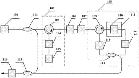
[0028] Embodiment 1: This embodiment provides a device and method for a multi-bandwidth and high-frequency tunable microwave signal source. Such as figure 1 As shown, the present embodiment includes a laser 100, the output light of which is divided into two beams by a coupler 101 (95:5), wherein 95% of the light enters the frequency shift unit 102, and the backscattered signal output from the unit 102 passes through The erbium-doped fiber amplifier unit 107 is amplified as the pumping light of the Brillouin ring cavity laser unit 108. In order to control the input optical power of the optical amplifier unit 107, an optical attenuator 106 is added between the frequency shifting units 102 and 107, from The optical signal output by the Brillouin laser unit 108 and the local oscillator light are coupled into the balanced photodetector 116 through the coupler 115 (50:50). The frequency shifting unit 102 includes a circulator 103 , a tunable optical attenuator 104 and a common sing...

Embodiment 2

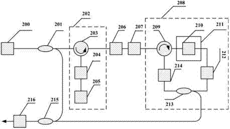
[0029] Embodiment 2: This embodiment provides a device and method for a multi-bandwidth and high-frequency tunable microwave signal source. Such as figure 2 As shown, this embodiment includes a laser light source 200 , a coupler 201 , a frequency shift unit 202 , a tunable attenuator 206 , an erbium-doped fiber amplifier 207 , a Brillouin laser unit 208 , a coupler 215 , and a photodetector 206 . The circulator 203 and the adjustable attenuator 204 , the light output from the adjustable attenuator enters into the ordinary single-mode optical fiber 205 . Circulator 209, polarization controller 214, coupler 213 (80:20), isolator 212, optical fiber 210 and stress controller 211; circulator 215, coupling on the second coupler 215 (50:50), through photodetection device 216.

[0030] and figure 1 Compared with the device and method of the multi-bandwidth high-frequency tunable microwave signal source, the difference lies in that the Brillouin ring cavity laser unit 208 controls ...

Embodiment 3

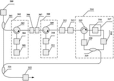
[0031] Embodiment 3: This embodiment provides a device and method for a multi-bandwidth and high-frequency tunable microwave signal source, such as image 3 shown, with figure 1 Compared with the device and method of the multi-bandwidth high-frequency tunable microwave signal source, the difference is that the frequency shifting unit part is composed of multiple frequency shifting units 302 and 308, or more frequency shifting units, so that Higher frequency tunable microwave signal sources are available.


PUM


Abstract

A device capable of generating multi-bandwidth high-frequency tunable microwave signals comprises a laser device (100), a coupler (101), a frequency shift unit (102), an optical fiber amplifier (107), a third coupler (115), a photoelectric detector (116) and a Brillouin ring cavity laser unit (108). Laser light generated by the laser device is split to two beams by the coupler, one beam of laser light serves as pumping light to enter the frequency shift unit, the Brillouin ring cavity laser unit comprises a second circulator, a polarization controller, a second coupler, an optical fiber unit and a temperature or stress controller unit, light outputted by the optical fiber amplifier is switched into a first port of the second circulator, an optical isolator is added in the transmission direction of Brillouin scattering signals, the Brillouin scattering signals are outputted from a split arm of the second coupler, and the outputted Brillouin scattering signals and local oscillating light outputted by the coupler are coupled on the third coupler and are converted into the microwave signals for output by the aid of the photoelectric detector.

Description

technical field [0001] The invention relates to a device and method for generating multi-bandwidth and high-frequency tunable microwave signals, which are mainly used in the technical fields of wireless sensor network, optical fiber communication, microwave photonics and the like. Background technique [0002] With the rapid development of information technology, data services are growing explosively. During this process, a large amount of high-speed information needs to be generated, transmitted, exchanged and obtained. Therefore, the requirements for bandwidth increase accordingly. At present, technology based on digital electronics has approached the processing limit of electronic devices, and it is becoming more and more difficult to further improve the processing speed of equipment. The development speed of electronic technology has been far behind the rapid growth of information capacity, and problems such as bandwidth limitation and electronic bottleneck of switching ...

Claims


Application Information

Patent Timeline
Patent Type & Authority Applications(China)
IPC IPC(8): H01S1/02
Inventor 王如刚陈荣陈益飞
Owner 浙江依网科技信息工程有限公司
Why Eureka
Try Eureka