Control method for access of dynamic reactive power compensation device to power transmission grid

A technology of compensation device and control method, applied in reactive power compensation, AC network voltage adjustment, single-network parallel feeding arrangement, etc., can solve problems such as no one raised

Active Publication Date: 2013-01-02
北京智中能源互联网研究院有限公司
View PDF2 Cites 25 Cited by
  • Summary
  • Abstract
  • Description
  • Claims
  • Application Information

AI Technical Summary

Problems solved by technology

However, no one has proposed a control

Method used


Image

  • Control method for access of dynamic reactive power compensation device to power transmission grid
  • Control method for access of dynamic reactive power compensation device to power transmission grid
  • Control method for access of dynamic reactive power compensation device to power transmission grid

Examples


Embodiment Construction

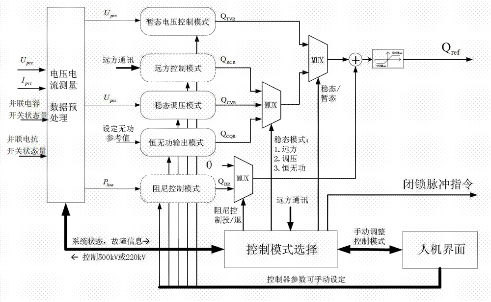
[0057] The control method for connecting the dynamic reactive power compensation device to the transmission network proposed by the present invention, its flow chart is as follows figure 1 shown, including the following steps:

[0058] (1) When a control cycle of the dynamic reactive power compensation device arrives, measure the effective value U of the voltage at the grid-connected point where the dynamic reactive power compensation device is connected to the transmission network in real time pcc and current rms value I pcc ;

[0059] (2) When the above-mentioned control cycle arrives, detect the switching status of the parallel capacitor and the parallel reactance in the substation where the dynamic reactive power compensation device is located;

[0060] (3) Set the voltage reference value U of the grid-connected point where the dynamic reactive power compensation device is connected to the transmission network ref , generally set as 500kV or 220kV or 35kV, according to ...


PUM


Abstract

The invention relates to a system control method for a dynamic reactive power compensation device and belongs to the technical field of grid safety and stable control of a power system. The method includes: according to voltage and current of the dynamic reactive power compensation device accessed to the power transmission grid, switching states of parallel compensation equipment in a substation and manual setup of operators, quickly calculating reactive power requirement values of each functional mode of the dynamic reactive power compensation device, and determining which output of the functional modes can be selected by the dynamic reactive power compensation device to serve as reactive power reference instruction values. The method has the advantages of distinct control structure, simplicity in implementation and the like and overcomes the defect of single control function of a traditional control method. In addition, the control method can be applied to stable control of the power system, and voltage stability and dynamic stability of the power transmission grid can be improved.

Description

technical field [0001] The invention relates to a control method for connecting a dynamic reactive power compensation device to a power transmission network, and belongs to the technical field of power grid stability control of an electric power system. Background technique [0002] Dynamic var compensation device is a typical application of modern power electronics technology in power system, including static var compensator (SVC) with thyristor as switching device and static synchronous device with turn-off device (IGBT, IGCT) as switching device. Reactive power generator (STATCOM), when these devices are applied to the transmission network, they can dynamically provide voltage support after system faults, ensure the stability of the bus voltage, improve the transient stability level of the power system, and prevent transient voltage collapse caused by Load loss and large-scale vicious power outages. In addition, STATCOM can also realize functions such as daily automatic ...

Claims


Application Information

Patent Timeline
IPC IPC(8): H02J3/16H02J3/50
CPCY02E40/34Y02E40/30
Inventor 袁志昌
Owner 北京智中能源互联网研究院有限公司
Why Eureka
Try Eureka