Distributed antenna structure applied to high-speed railway

A technology for distributed antennas and high-speed railways, applied in diversity/multi-antenna systems, combinations of antenna units with different polarization directions, space transmit diversity, etc., can solve problems affecting the communication quality of high-speed high-speed trains and difficulties in railway wireless communication

Inactive Publication Date: 2013-01-02
CHINA RAILWAY SIGNAL & COMM
View PDF1 Cites 19 Cited by
  • Summary
  • Abstract
  • Description
  • Claims
  • Application Information

AI Technical Summary

Problems solved by technology

And due to the geographical concentration of passengers on the high-speed train, when the high-speed train crosses the edge of the cell, user group switching will occur
These have greatly affected the communication quality on high-speed high-speed trains
Taking the construction of GSM-R base stations that are widely used

Method used


Image

  • Distributed antenna structure applied to high-speed railway
  • Distributed antenna structure applied to high-speed railway
  • Distributed antenna structure applied to high-speed railway

Examples


Embodiment 1

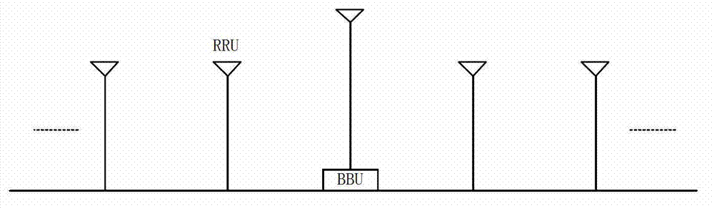
[0037] In the first method, that is, the simple transmit diversity implementation method, such as figure 2 , taking the combination of space-time block codes to achieve diversity gain as an example. The antennas along the line are numbered evenly and oddly, and the information codes sent by the odd-numbered antennas are consistent, while the information coded by the even-numbered antennas adopts its corresponding space-time grouping form. That is, if the odd serial number sends information coded as - s 2 * s 1 * , Even number sent information is coded as s 1 ...

Embodiment 2

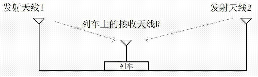
[0044] In the second method, the implementation method of transmit diversity using directional antennas, such as image 3 As shown, two antennas are provided at each RRU, facing one end of the rail respectively. When the train is running in the middle of the rails, only the signals of the directional antennas facing the train at two adjacent RRUs can be received by the directional receiving antennas on the train respectively, and the signals of other antennas can basically be ignored.

[0045] Suppose the energy of a signal received by the train is E 1 , the weighting coefficient is α 1 , the energy of the other signal is E 2 , the weighting coefficient is α 2 , then the equivalent amplitude of the composite signal is: α 1 E. 1 -α 2 E. 2 . Assume the train with energy E 1 When one end is closer, then E 1 >>E 2 , the receiver mainly relies on E 1 Make a judgment; when the train is running in the middle of two adjacent RRUs, there will be E 1 ~E 2 , α 1 ~α 2 , th...

Embodiment 3

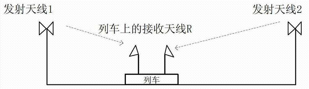
[0047] In the third method, that is, using polarized antennas and transmit diversity implementation methods, such as Figure 4 As shown, the horizontally polarized antenna and the vertically polarized antenna are arranged alternately, so that the train travels to any section of the rail track, and the antennas at the two adjacent RRUs are horizontally polarized and vertically polarized. Since the two polarization modes are orthogonal to each other, the interference is minimal under normal circumstances, and the two polarized receiving antennas on the train will be independent of each other and receive the two signals without interfering with each other.

[0048] Suppose the energy of a signal received by the train is E 1 , the weighting coefficient is α 1 , the energy of the other signal is E 2 , the weighting coefficient is α 2 , then the equivalent amplitude of the composite signal is: α 1 E. 1 -α 2 E. 2 . Assume the train with energy E 1 When one end is closer, the...


PUM


Abstract

A distributed antenna structure applied to a high-speed railway is characterized in that more than one base station is arranged along the high-speed railway, a plurality of distributed antennas are erected equidistantly and symmetrically along the high-speed railway by centering on one base station, the radius of the effective coverage range of each distributed antenna is larger than or equal to the gap between each two adjacent distributed antennas, the distributed antennas are connected with the base stations through optical fibers, each base station comprises a baseband processing unit band, each distributed antenna has a remote radio-frequency unit, and antennas of high-speed trains are communicated with the distributed antennas. The distributed antenna structure applied to the high-speed railway achieves space diversity gain, improves communication reliability, increases communication rate, is remarkably effective in improvement on communication performance and experience and has a wonderful application prospect in future.

Description

technical field [0001] The invention relates to the technical field of wireless communication, in particular to a distributed antenna architecture applied to high-speed railways. Background technique [0002] After my country's railways have undergone several substantial speed increases, high-speed trains are running faster and faster. The speed of high-speed trains on high-speed railways currently in operation has reached and exceeded 350km / h, and the requirements for the type and quality of communication services in high-speed environments are also getting higher and higher, which undoubtedly puts forward more stringent requirements for railway wireless communication. [0003] Current wireless access is mainly for low-speed mobile scenarios. When a mobile terminal switches rapidly between cells and the transit time is less than the minimum delay for the system to process the switch, the mobile terminal will drop calls. And due to the geographical concentration of passenge...

Claims


Application Information

Patent Timeline
IPC IPC(8): H04B7/04H01Q21/24
Inventor 郭斐斐徐建华郑刚蒋定顺杨杰朱文浩熊箭归琳刘勃马文峰
Owner CHINA RAILWAY SIGNAL & COMM
Why Eureka
Try Eureka