Modular heat pipe heat exchanger

A technology of heat exchangers and heat pipes, applied in heat exchange equipment, heat exchanger types, indirect heat exchangers, etc., can solve problems such as time-consuming, high operating costs, and production losses

Active Publication Date: 2015-02-04
PAUL WURTH SA +2
View PDF6 Cites 0 Cited by
  • Summary
  • Abstract
  • Description
  • Claims
  • Application Information

AI Technical Summary

Problems solved by technology

Due to the large number of heat pipes arranged in such heat exchangers, the cleaning of said heat pipes is usually a very time-consuming process
Furthermore, the difficulty of accessing various areas in the heat exchanger does not facilitate the cleaning process
Prolonged downtime periods inevitably lead to lost production and high operating costs

Method used


Image

  • Modular heat pipe heat exchanger
  • Modular heat pipe heat exchanger
  • Modular heat pipe heat exchanger

Examples


Embodiment Construction

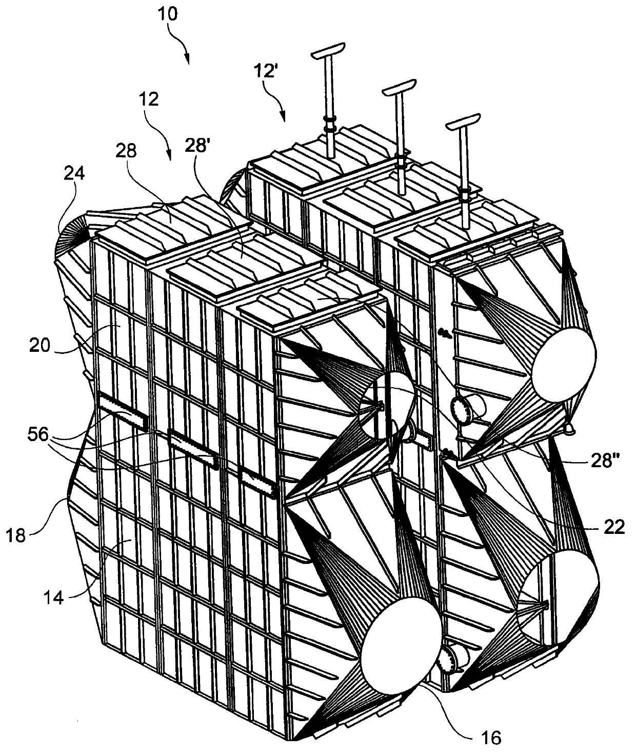
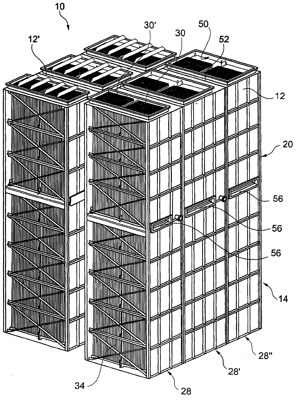
[0022] figure 1 A preferred embodiment of a heat pipe recovery system 10 according to the invention with two heat pipe heat exchangers 12, 12' is shown. One of the heat exchangers 12, 12' may be used to preheat the combustion gases, while the other of the heat exchangers 12, 12' may be used to preheat the combustion air.

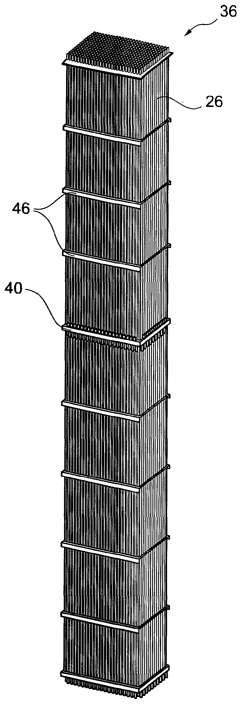
[0023] Each heat exchanger 12, 12' includes a first chamber 14 having a first port 16 and a second port 18 and a second chamber 20 having a third port 22 and a fourth port 24. In the embodiment shown in the figures, the second chamber 20 is arranged vertically above the first chamber 14 . A plurality of heat pipes 26 (typically several thousand) are arranged vertically in said first and second chambers 14 , 20 . These heat pipes 26 generally extend over the entire height of the second chamber 20, passing through the separating wall (in figure 1 not visible in ) from the second chamber 20 to the first chamber 14 and extends over the entire height of t...


PUM


Abstract

A heat pipe heat exchanger (12, 12') for transferring heat from a hot gas to a cold gas comprises a housing with a first chamber (14) for feeding a hot gas therethrough; a second chamber (20) for feeding a cold gas therethrough; and a plurality of heat pipes (26) extending between the first chamber (14) and the second chamber (20) for transferring heat from the hot gas to the cold gas. The heat pipe heat exchanger (12, 12') further comprises one or more heat pipe cartridges (36) removably arranged in the housing. Each heat pipe cartridge (36) comprises a frame (38) with a support panel (40) for supporting a plurality of heat pipes (26); the support panel (40) being arranged such that, when the heat pipe cartridge (36) is arranged in the housing, the support panel (40) cooperates with a separation wall (32) between the first chamber (14) and the second chamber (20) to form a gas-tight partition between the first and second chambers (14, 20). The heat pipes (26) traverse the support panel (40) and are secured thereto in a gas-tight manner.

Description

technical field [0001] The present invention generally relates to a heat pipe heat exchanger for transferring heat from a hot gas to a cold gas, in particular for use in heat recovery units for preheating combustion air and / or combustion gases. Background technique [0002] Heat recovery systems are used in various industries to recover heat from one medium and transfer it to another. Using excess heat from one gas to preheat another gas reduces energy consumption and is therefore more environmentally friendly. [0003] One such heat recovery system is for example disclosed in US 4,434,004, which relates to a method for recovering and reusing heat from hot waste gases, especially waste gases from metallurgical processes and from warm gases and equipment. The warm or hot exhaust gases transfer their retained heat to the lower part of the vertically placed heat pipes. Cool air or cold air is then directed through the upper part of the heat pipe, thus transferring the heat o...

Claims


Application Information

Patent Timeline
Patent Type & Authority Patents(China)
IPC IPC(8): F28D15/02
CPCF28D21/001F28D15/0275F28F2280/02F28F19/00F28D1/00F28D9/00F28D15/02F28F3/02
Inventor 弗兰克·蒂尔诺伯特·考滕布格尔哈尼·埃尔-卡萨斯埃米尔·洛纳尔迪法比奥·加尔布金奥斯特凡诺·奥利维里卢卡·斯帕多尼
Owner PAUL WURTH SA
Why Eureka
Try Eureka