End cover box for horizontal centrifugal casting of roll

A technology of centrifugal casting and end caps, which is applied in the field of end cap boxes, can solve the problems of poor quality stability of the refractory cement layer, easy slag inclusion in the inner and outer bonding layers, and uneven thickness of the outer layer of the casting blank, so as to shorten the use preparation period and reduce the The effect of drying energy consumption and product quality stability

Active Publication Date: 2015-05-13
SINOSTEEL XINGTAI MACHINERY & MILL ROLL
View PDF6 Cites 2 Cited by
  • Summary
  • Abstract
  • Description
  • Claims
  • Application Information

AI Technical Summary

Problems solved by technology

[0003] At present, the end cover box used for centrifugal casting of roll blanks is an iron end cover box, and a refractory cement layer with a thickness of 50mm~150mm is made inside the end cover box, and the refractory cement layer is dried for production and use, but the refractory cement layer requires Long-term health preservation and drying, the preparation period is long, and it needs to be made 6 days in advance, which is not conducive to improving production efficiency; because the refractory cement layer is thicker, the temperature of the end cover box when drying the refractory cement layer needs to be above 300 °C Allow to dry for 72 hours before use
The drying temperature is high, and it takes a long time to dry, which consumes a lot of energy; in addition, the quality stability of the refractory cement layer is poor. After the core molten iron is poured into the cavity, the molten iron will react violently with the refractory cement layer. , resulting in uneven thickness of the outer layer of the casting blank, and slag inclusions are prone to appear in the inner and outer bonding layers, which brings potential risks to product quality

Method used


Image

  • End cover box for horizontal centrifugal casting of roll

Examples


Embodiment 1

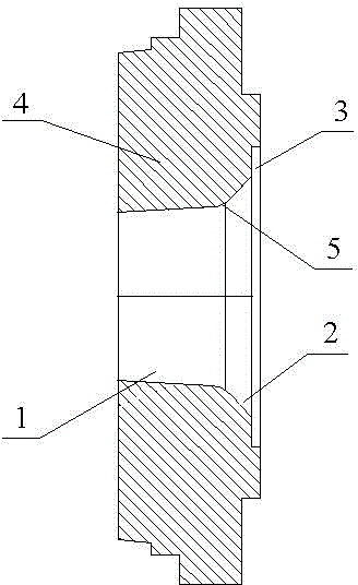
[0018] In the present invention, the metal-shaped end cover box is made of carbon steel, and the end cover box 4 is provided with a through hole for pouring molten iron along the central axis. The structure is as figure 1 Shown. The through hole is a horn-like three-step stepped hole, the first stepped hole and the second stepped hole are both conical, the taper angle of the first stepped hole 1 is 10°, and the taper angle of the second stepped hole 2 is 120 °, the third stepped hole 3 is a straight hole, the first stepped hole 1 and the second stepped hole 2 are transitionally connected by a round corner 5, and the radius of the round corner 5 is 10 mm. The inner surface of the through hole of the end cover box 4 is provided with a thread, the depth of the thread is 5mm, and the width is 3mm.

[0019] Before the end cover box 4 is used, the inner surface of the through hole of the end cover box 4 is coated with a certain thickness of refractory cement. Other types of refractory...

Embodiment 2

[0022] The structure of the end cover box 4 in this embodiment is basically the same as that of Embodiment 1, with the difference that: the taper angle of the first stepped hole is 20°; the taper angle of the second stepped hole is 100°.


PUM

PropertyMeasurementUnit
radiusaaaaaaaaaa
depthaaaaaaaaaa
widthaaaaaaaaaa

Abstract

The invention discloses an end cover box for horizontal centrifugal casting of a roll. The end cover box is made of carbon steel, a through hole for casting of melted iron is arranged on the end cover box along the central axis and is a three-stage stepped hole in a trumpet shape, the first stepped hole and the second stepped hole are in a cone shape, the cone angle of the first stepped hole is 10-20 degrees, the cone angle of the second stepped hole is 100-120 degrees, and the third stepped hole is a straight hole; and thread lines which are 5mm in depth and 3mm in width are arranged on the inner surface of the through hole. According to the end cover box, adhesion of refractory coating is facilitated, washing of iron liquid to the refractory coating is reduced in a casting process, the service life of the end cover box is prolonged, energy resources can be saved, the working efficiency is improved, the production cost is reduced, and quality of products is guaranteed.

Description

Technical field [0001] The present invention relates to a new-shaped process device used in the technical field of centrifugal casting, in particular to an end cover box used in pouring. Background technique [0002] Casting roll is a kind of casting that needs to bear large load and surface wear resistance. Centrifugal casting is currently the main production process for rolls. In the process of centrifugal casting to produce roll blanks, horizontal centrifugal casting machines are widely used. The cavity of the horizontal centrifugal casting machine is arranged horizontally. In the casting production process, one end cover box is set at the front and back ends of the mold, so that a cavity is formed between the mold and the front and rear end cover boxes. When pouring, the casting is first placed on the centrifugal casting machine, and molten iron is poured into it. In the rotating cavity, the molten iron is used to form the outer layer of the roll on the inner surface of th...

Claims


Application Information

Patent Timeline
Patent Type & Authority Patents(China)
IPC IPC(8): B22D13/10B22D13/02
Inventor 刘建朝刘路军石平兰
Owner SINOSTEEL XINGTAI MACHINERY & MILL ROLL
Why Eureka
Try Eureka