
Piezoelectric element drive circuit and liquid ejecting apparatus

A piezoelectric element and drive circuit technology, applied in the direction of electrical components, circuits, piezoelectric/electrostrictive/magnetostrictive devices, etc., can solve the problem of large-scale drive circuits

Inactive Publication Date: 2013-01-09
SEIKO EPSON CORP
View PDF9 Cites 13 Cited by
  • Summary
  • Abstract
  • Description
  • Claims
  • Application Information

AI Technical Summary

Problems solved by technology

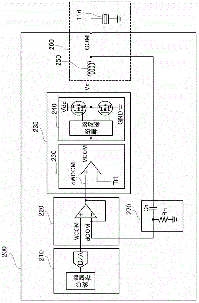
[0006] However, in the above-mentioned conventional technology, in addition to a power source for generating a voltage for deforming the piezoelectric element, a power source for generating a relatively low voltage for eliminating residual strain is also required, so the drive circuit for the piezoelectric element is increased in size. The problem

Method used


Image

  • Piezoelectric element drive circuit and liquid ejecting apparatus
  • Piezoelectric element drive circuit and liquid ejecting apparatus
  • Piezoelectric element drive circuit and liquid ejecting apparatus

Examples


Embodiment Construction

[0033] Next, in order to clarify the contents of the present invention described above, examples will be described in the following order.

[0034] A. Device structure:

[0035] B. The circuit structure of the piezoelectric element drive circuit:

[0036] C. Action of piezoelectric element drive circuit:

[0037] D. Variations:

[0038] A. Device structure:

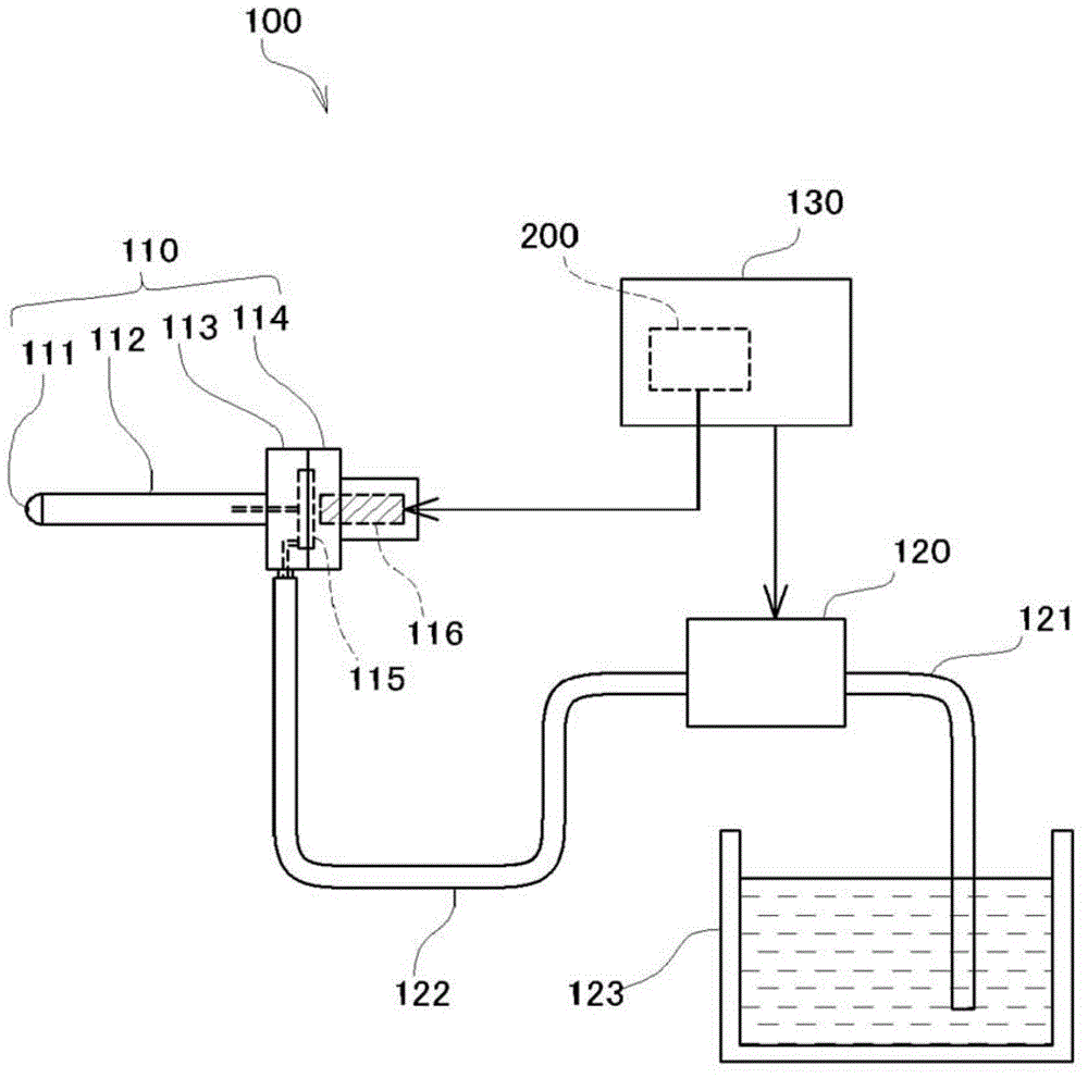
[0039] figure 1 It is an explanatory diagram showing the configuration of the fluid ejection device 100 incorporating the piezoelectric element drive circuit 200 of the present embodiment. As shown in the figure, the fluid injection device 100 is roughly divided into the following parts: an injection unit 110 that injects fluid, a fluid supply unit 120 that supplies the fluid injected from the injection unit 110 to the injection unit 110, and controls the injection unit 110 and the fluid injection unit 110. The control unit 130 and the like for the operation of the supply unit 120 .

[0040] The injection unit 110 i...


PUM


Abstract

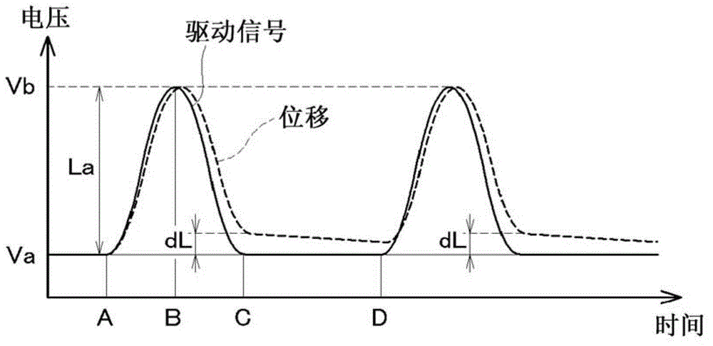
A drive waveform signal as a reference of a drive signal to be applied to a piezoelectric element is power-amplified, and the drive signal after passing through a coil is applied to the piezoelectric element. A resonant circuit is formed of the coil and the piezoelectric element, and a resonant peak is suppressed by performing a phase advance compensation of the drive signal and by performing a negative feedback. At this time, the degree of suppression of the peak is adjusted so that a slight reverse voltage is generated. Since this can eliminate residual distortion of the piezoelectric element by the reverse voltage, even when driving is performed at a high repetition frequency, the original amount of deformation can be ensured. Besides, the circuit does not become complicated.

Description

technical field [0001] The present invention relates to techniques for driving piezoelectric elements. Background technique [0002] Piezoelectric elements represented by PZT (lead zirconate titanate) have the characteristic of stretching when a positive voltage is applied and shrinking when the positive voltage is released (so-called piezoelectric characteristics). By utilizing this characteristic, it is possible to configure an actuator that responds at a high response speed by application of a drive voltage, is compact, and generates a large force. Therefore, piezoelectric elements are mounted as actuators and the like in fluid ejection devices typified by inkjet printers, and are widely used industrially. [0003] In addition, the piezoelectric element has a property that, for example, after stretching by applying a positive voltage, residual strain is generated when the voltage is released to shrink. If the piezoelectric element is temporarily placed in a state where ...

Claims


Application Information

Patent Timeline
Patent Type & Authority Applications(China)
IPC IPC(8): B41J2/045H10N30/20
CPCA61M5/14276A61B17/00H01L41/042H10N30/802
Inventor 大岛敦
Owner SEIKO EPSON CORP
Learn More