Screw-free plastic disc type rotary injection method and device

A plastic disc and disc type technology, which is applied to devices and coatings for coating liquid on the surface, can solve the problems of low storage metering accuracy, large injection motion inertia, and high injection energy consumption, and achieve accurate storage metering, The effect of low manufacturing cost and high measurement accuracy

Active Publication Date: 2013-04-17
SOUTH CHINA UNIV OF TECH +1
View PDF1 Cites 0 Cited by
  • Summary
  • Abstract
  • Description
  • Claims
  • Application Information

AI Technical Summary

Problems solved by technology

[0003] The purpose of the present invention is to provide a plastic disc rotary injection method without screw to overcome the complex structure, high cost, low accuracy of storage and measurement caused by linear motion in the process of material storage, injection and pressure holding in the prior art. Disadvantages such as high energy consumption of injection and large inertia of injection movement

Method used


Image

  • Screw-free plastic disc type rotary injection method and device
  • Screw-free plastic disc type rotary injection method and device
  • Screw-free plastic disc type rotary injection method and device

Examples


Embodiment 1

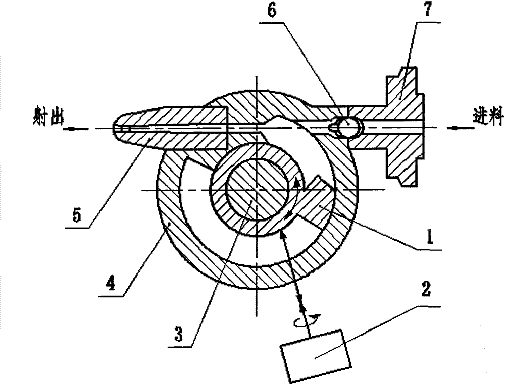
[0022] As shown in Figure 1, the plastic disc rotary injection device includes an injection piston 1, a motor 2, a support shaft 3, a disc storage cylinder 4, a nozzle 5, a control valve 6 and a connecting flange 7; the disc storage cylinder 4 There is an annular groove, the injection piston 1 is set on the support shaft 3, and connected with the motor 2, the piston head of the injection piston 1 is placed in the annular groove, and can be rotated at a certain angle around the center of the disc storage cylinder 4 in the annular groove. Rotational movement. A nozzle 5 is provided on the peripheral edge of the disc storage cylinder 4, and the channel of the nozzle 5 communicates with the annular groove; a channel is also provided on the peripheral edge of the disc storage cylinder 4, and the channel is connected with the connecting flange 7. On the channel, A control valve 6 is provided.

[0023] The working process of this embodiment is:

[0024] When storing material, open ...

Embodiment 2

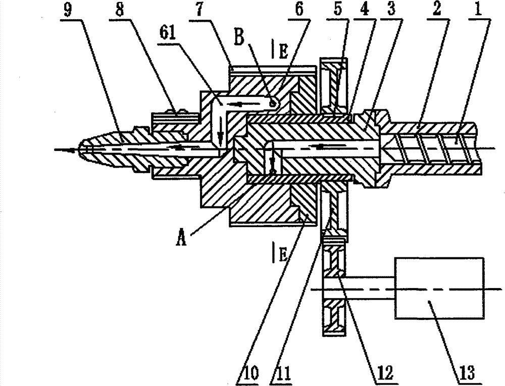
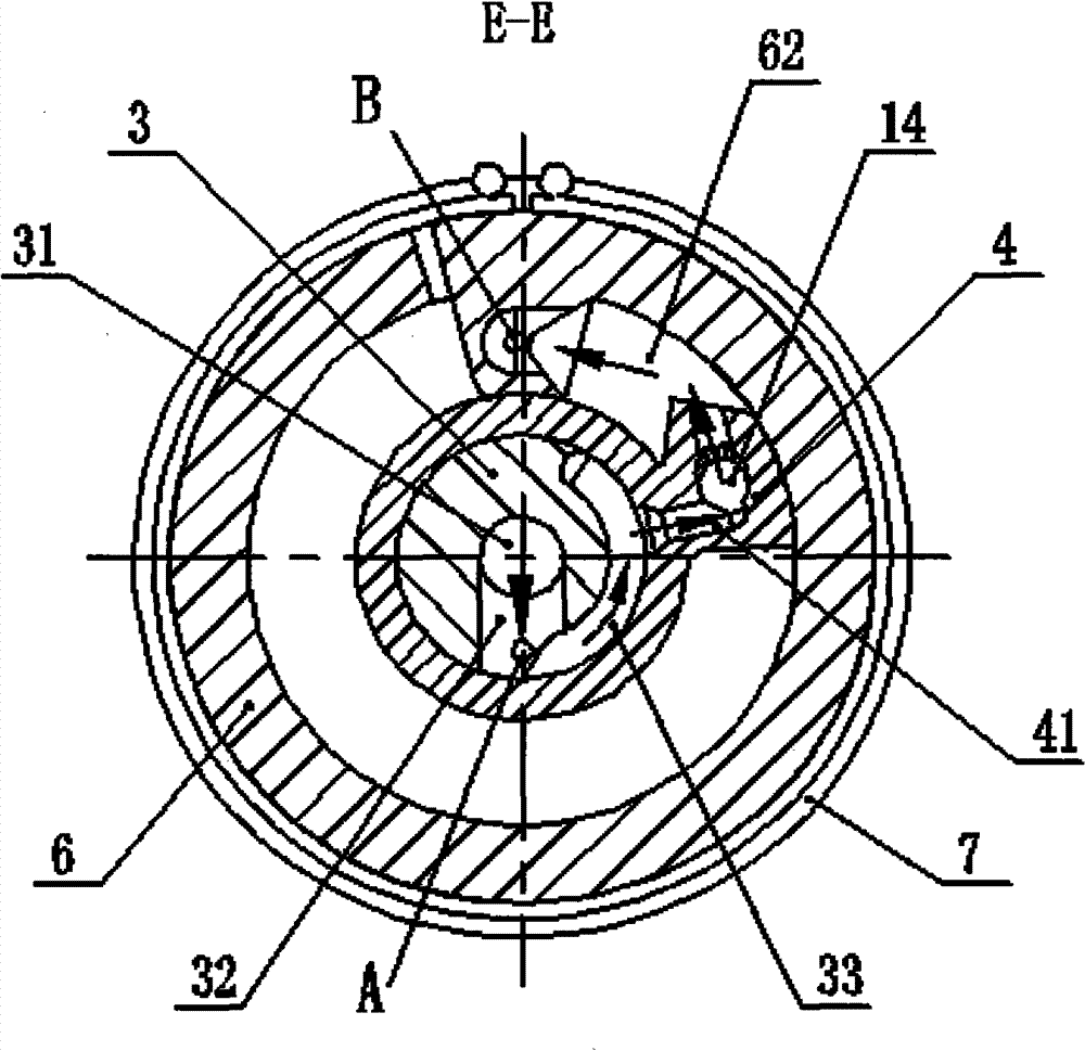
[0028] Such as figure 2 , 3 As shown, the screwless plastic disc rotary injection device includes a support shaft 3, an injection piston 4, a key 5, a disc storage cylinder 6, a metering heating ring 7, a nozzle heating ring 8, a fixed flange 10, and a driven gear 11, driving gear 12, motor 13 and check ball 14. The outer periphery of the injection piston 4 is provided with a disc storage cylinder 6, a fixed flange 10 and a driven gear 11 in sequence; the driven gear 11 is connected with the injection piston 4 through a key 5, the driven gear 11 meshes with the driving gear 12, and the driving gear 12 is connected with the output shaft of motor 13. The support shaft 3 is located in the injection piston 4, and the support shaft 3 is provided with such Figure 4 As shown in the axial flow channel 31, the radial flow channel 32 and the circumferential flow channel 33, one end of the support shaft 3 is connected to the barrel 2, and the other end of the support shaft 3 is conn...


PUM


Abstract

Disclosed are a non-screw plate type rotary plastic injection method and the apparatus thereof. A piston which is arranged in circular groove of a round plate and rotatable about center of the plate is used to complete the processes of plastic feeding, injection and pressure holding. The plate type rotary injection apparatus consists of a plate type storage cavity (4) having a circular groove on its round plate, an injection piston (1) rotatable about the plate type storage cavity (4), a support shaft (3), a nozzle (5) and so on. To complete the process of filling plastic materials, the plastic melt enters the plate type storage cavity (4) propelling the injection piston rotates and enlarges the storage cavity. An external force is applied to drive the injection piston (1) to rotate reversely, so as to eject the material in the plate type storage cavity out through the nozzle (5) and into the mould cavity. The torque of the injection piston (1) is maintained, so that the pressure in the mould cavity is maintained and the material shrinkage is compensated. The injection apparatus is featured in its small scale, accurate measurement of material to be stored, low energy consumption of injection and low inertia in injection movement.

Description

technical field [0001] The invention relates to a plastic injection molding method and its equipment, in particular to a screwless plastic disc rotary injection method and device. Background technique [0002] Plastic injection molding machine is the main processing equipment for plastic molding. The injection molding process includes plasticization, material storage, injection filling, pressure holding, cooling, mold opening and ejection, among which the processes of material storage, injection filling, and pressure holding are completed in the injection device. In the traditional plunger type injection device or screw one-line injection device, the material (plastic melt) continuously enters the front end of the storage barrel during material storage, and pushes the plunger or screw back in a straight line, and the storage volume increases to complete the storage. ;During injection, the plunger or screw moves forward in a straight line under the drive of external force, p...

Claims


Application Information

Patent Timeline
Patent Type & Authority Patents(China)
IPC IPC(8): B29C45/53B29C45/58
CPCB29C45/464B29C45/46B05C5/0233
Inventor 瞿金平晋刚殷小春何和智
Owner SOUTH CHINA UNIV OF TECH
Why Eureka
Try Eureka