Self-oscillation pulsed liquid-gas jet pump

A technology of liquid-air jet pump and self-excited oscillation, which is applied in jet pumps, pumps, non-volume pumps, etc., can solve the problems of low energy transfer efficiency and limit popularization and application, and achieve simple structure, high efficiency, and sufficient liquid-gas mixing Effect

Inactive Publication Date: 2013-01-09
SHANGHAI UNIV
View PDF7 Cites 24 Cited by
  • Summary
  • Abstract
  • Description
  • Claims
  • Application Information

AI Technical Summary

Problems solved by technology

[0002] The liquid-air jet pump has the advantages of no moving parts, simple structure, reliable operation, and convenient installation. It is suitable for special working conditions such as...

Method used


Image

  • Self-oscillation pulsed liquid-gas jet pump

Examples


Embodiment 1

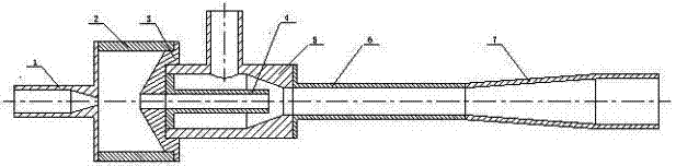
[0014] see figure 1 , the self-excited oscillation pulse liquid-air jet pump includes an upper nozzle (1), a self-excited oscillation chamber (2), a collision body (3), a lower nozzle (4), a suction chamber (5), a throat (6), The diffusion pipe (7), characterized in that the upper nozzle (1), the self-excited oscillation chamber (2), the collision body (3), and the lower nozzle (4) are sequentially connected to form a self-excited oscillation pulse jet nozzle; the self-excited oscillation The pulse jet nozzle, the suction chamber (5), the throat pipe (6), and the diffusion pipe (7) are connected in sequence to form a jet pump.

Embodiment 2

[0016] This embodiment is basically the same as Embodiment 1, and the special feature is: the self-excited oscillating pulse liquid-air jet pump, which is characterized in that: one end of the collision body (3) is designed as a concave hole, and is directly connected to the suction chamber ( 5) One end is connected; the lower nozzle (4) is located inside the suction chamber (5); the ratio of the area of ​​the lower nozzle (4) to the area of ​​the throat (6) is 1:3-8; the throat (6) ) ratio of inner diameter to length is 1:6-8; the ratio of cavity length to cavity diameter of the self-excited oscillation cavity (2) is 1:0.4-0.7; the upper end of the collision body (3) is a cone, the The taper of the cone is 120°±10°; the diameter ratio of the upper nozzle (1) and the lower nozzle (4) is 1:2.0~2.2;

Embodiment 3

[0018] Such as figure 1 As shown, the self-excited oscillation pulse liquid-air jet pump includes an upper nozzle (1), a self-excited oscillation chamber (2), a collision body (3), a lower nozzle (4), a suction chamber (5), a throat (6 ), diffusion pipe (7), characterized in that the upper nozzle (1), self-excited oscillation cavity (2), collision body (3), and lower nozzle (4) form a self-excited oscillation pulse jet nozzle; self-excited oscillation The pulse jet nozzle is connected to the suction chamber (5), and the lower nozzle (4) is located inside the suction chamber (5); one end of the throat pipe (6) is connected to the suction chamber (5), and the other end is connected to the diffuser pipe (7) to form a jet pump.

[0019] The working process of the self-excited oscillating pulse liquid-air jet pump is: the constant jet flow from the upper nozzle (1) enters the self-excited oscillation cavity (2), and the vorticity disturbance in the jet flow within a certain freque...


PUM


Abstract

The invention relates to a self-oscillation pulsed liquid-gas jet pump. The jet pump comprises an upper nozzle, a self-oscillation cavity, a collision body, a lower nozzle, a suction chamber, a throat pipe and a diffusion tube, wherein the upper nozzle, the self-oscillation cavity, the collision body and the lower nozzle are connected sequentially to form a self-oscillation pulsed jet nozzle; after passing through the self-oscillation pulsed jet nozzle, a main jet flow of high-pressure liquid is modulated into a pulsed jet flow and enters the suction chamber of a liquid-gas jet pump; and gas is introduced under the action of jet turbulent diffusion, and boosted and exhausted through the diffusion tube after mixing and energy exchange in the throat pipe. The self-oscillation pulsed liquid-gas jet pump has the advantages that the self-oscillation pulsed jet nozzle and the liquid-gas jet pump are combined, and the main jet flow is changed into pulsed jet flow through the self-oscillation pulsed jet nozzle, so that the mass transfer capability of the main jet flow is improved, and the efficiency of the liquid-gas jet pump is improved. The device is not provided with a motion part, simple in structure and reliable in operation, and is suitable for waste gas absorption and treatment, oil and gas exploitation, vacuumization, aeration and other application situations.

Description

technical field [0001] The invention belongs to liquid jet technology application equipment in fluid machinery, specifically a self-excited oscillating pulse liquid-air jet pump, which is a fluid machinery and mixing equipment that transfers energy and quality by using jet turbulence and diffusion, and is applied to waste gas absorption and treatment , oil and gas extraction, vacuuming, aeration and other fields. Background technique [0002] The liquid-air jet pump has the advantages of no moving parts, simple structure, reliable operation, and convenient installation. It is suitable for special working conditions such as high temperature, high pressure, and strong radiation. It is widely used in petroleum, chemical, fire, and environmental protection. The low energy transfer efficiency limits its further popularization and application. The efficiency of the liquid-air jet pump is the core issue in its design theory. How to improve the efficiency of the liquid-air jet pump...

Claims


Application Information

Patent Timeline
IPC IPC(8): F04F5/00
Inventor 陈磊刘树林刘彦峰杜伟王勇
Owner SHANGHAI UNIV
Why Eureka
Try Eureka