

Orthogonal double grating based synchronous phase shifting common-path interference microscopy detection device and detection method
A synchronous phase-shifting and interference microscopy technology, which is applied in the direction of measuring devices, optical devices, instruments, etc., can solve the problems of complex detection data processing and low measurement accuracy, and achieve strong real-time performance, high measurement resolution, Easy to operate and flexible effects
- Summary
- Abstract
- Description
- Claims
- Application Information
AI Technical Summary
Problems solved by technology
Method used
Image

Examples
specific Embodiment approach 1
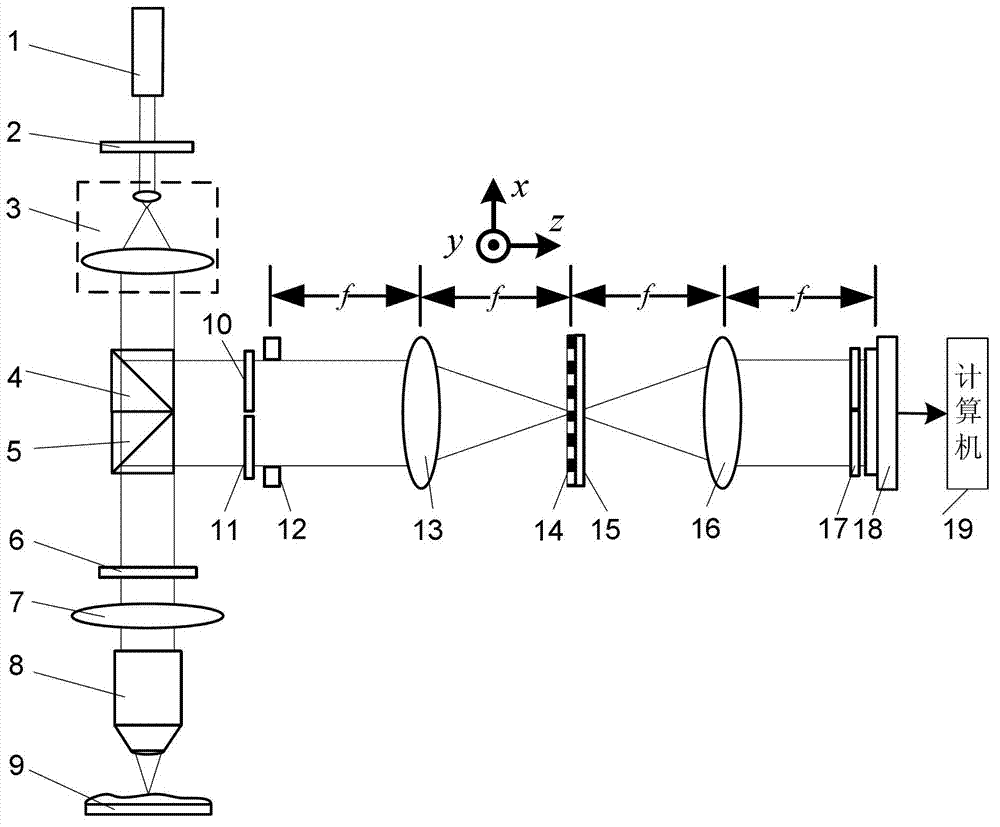
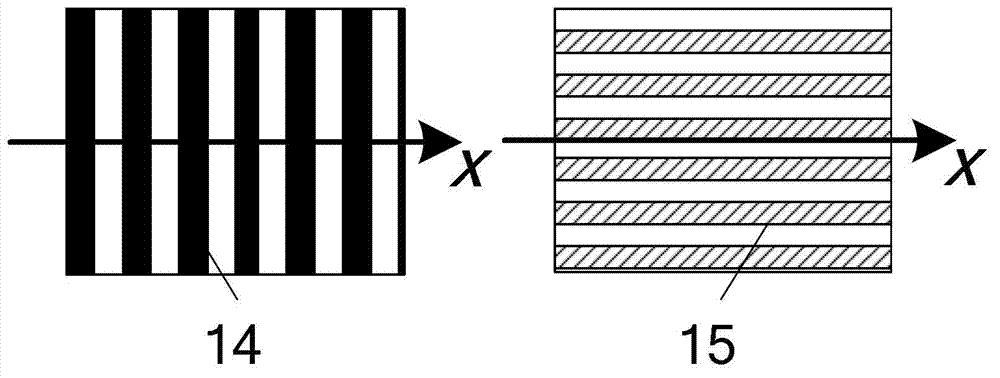
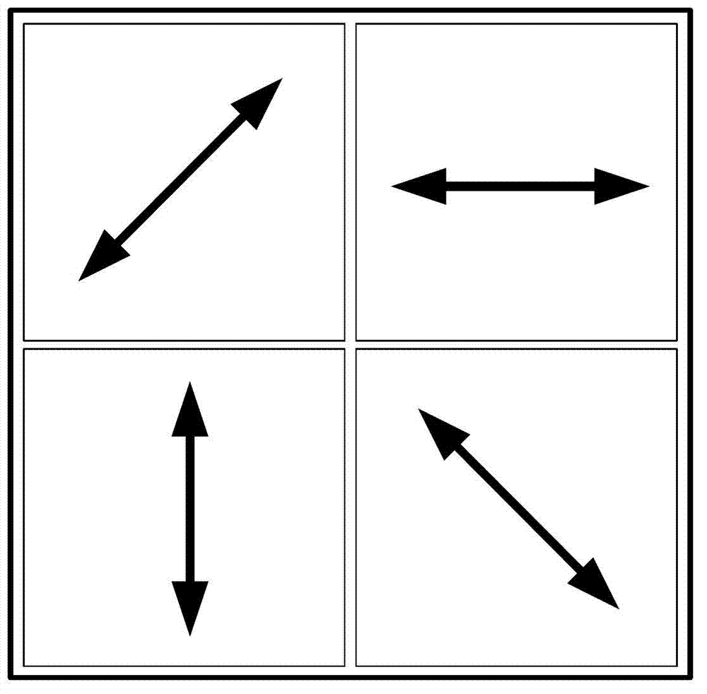
[0040] Specific implementation mode one: the following combination Figure 1 to Figure 4 Describe this embodiment, the synchronous phase-shifting common optical path interference microscope detection device based on orthogonal double gratings in this embodiment, it includes a light source 1, it also includes a linear polarizer 2, a collimating beam expander system 3, a first beam splitter Prism 4, second dichroic prism 5, first λ / 4 wave plate 6, correction objective lens 7, microscope objective lens 8, object to be measured 9, second λ / 4 wave plate 10, third λ / 4 wave plate 11, Rectangular window 12, first Fourier lens 13, one-dimensional period amplitude grating 14, one-dimensional period phase grating 15, second Fourier lens 16, four-quadrant polarizer group 17, image sensor 18 and computer 19, where λ is the light wavelength of the beam emitted by light source 1,
[0041] The one-dimensional period amplitude grating 14 and the one-dimensional period phase grating 15 form a ...
specific Embodiment approach 2
[0053] Specific embodiment two: this embodiment is a further description of embodiment one, the first dichroic prism 4 and the second dichroic prism 5 are non-polarizing dichroic prisms, the second λ / 4 wave plate 10 and the third λ / 4 wave The direction of the fast axis of sheet 11 is the same.
specific Embodiment approach 3
[0054] Specific Embodiment Three: This embodiment is a further description of Embodiment One. The first dichroic prism 4 and the second dichroic prism 5 are both polarizing dichroic prisms, and the second λ / 4 wave plate 10 and the third λ / 4 wave plate The directions of the fast axes of 11 are perpendicular to each other.
PUM
 Abstract
Description
Claims
Application Information