Weather resistance detection device for outer wall test piece
A detection device and weather resistance technology, applied in the field of measurement, can solve the problems affecting the development of new exterior wall materials and the improvement of construction technology, increase the detection cost and cycle, and the detection data is not comprehensive enough, so as to save manpower and time and shorten the test Cycle time, high reliability effect
- Summary
- Abstract
- Description
- Claims
- Application Information
AI Technical Summary
Problems solved by technology
Method used
Image
Examples
Embodiment 1
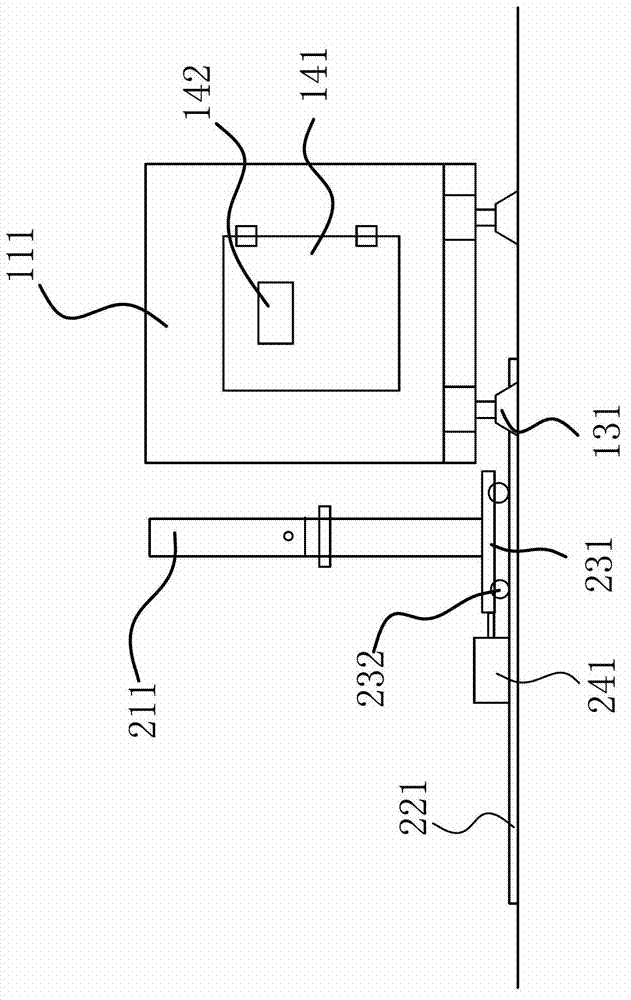
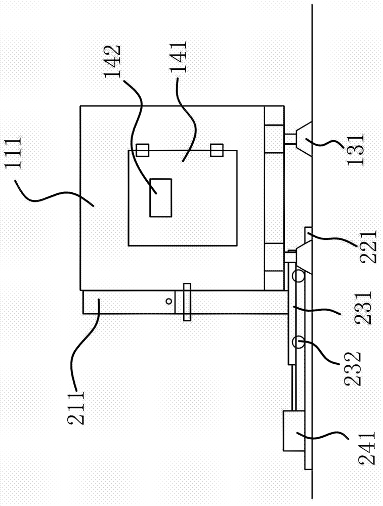
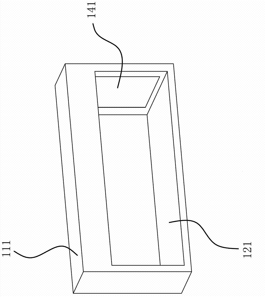
[0031] Such as Figure 1 to Figure 5 As shown, a weather resistance testing device for exterior wall specimens, such as figure 1 , figure 2 , image 3 As shown, it includes a square-shaped environmental box 111 and a frame 211 for fixing the outer wall test piece. The environmental box 111 is made of polyurethane thin steel plate composite material. The environmental box 111 is also equipped with a door 141. An observation hole 142 is opened on the door 141, and the observation hole 142 is sealed by glass; an inlet 121 is opened on the side of the environmental box 111, and a sealing strip is provided around the inlet 121 on the side of the environmental box 111, and the outer wall test piece can be against the inlet 121 On the sealing strip on the side of the surrounding environment box 111, the frame 211 is connected with a power guide mechanism that can push the frame 211 to abut against the side of the environment box 111 and enable the outer wall test piece on the fram...
Embodiment 2
[0041] The structure and principle of the present embodiment are basically the same as those of the first embodiment, except that the bottom of the environmental chamber 111 is fixed with a number of support feet 131 that can make it stand up, and there are four support feet 131 in the second embodiment, respectively Located at the four corners of the bottom of the environmental box 111, a gap is formed between the bottom of the supporting leg 131 and the bottom of the environmental box 111. The power guiding mechanism includes a guide rail 221, a bottom plate 231, a nut, a screw and a motor, and the guide rail 221 passes through the above-mentioned gap. and the guide rail 221 is perpendicular to the side of the environmental chamber 111 with the inlet 121, the frame 211 is fixed on the bottom plate 231, and the outer wall specimen fixed on the frame 211 is perpendicular to the guide rail 221, and the lower part of the bottom plate 231 is provided with several energy The roller...
Embodiment 3
[0043] The structure and principle of this embodiment are basically the same as that of Embodiment 1, the difference is that: Figure 6 As shown, there are two inlets 121 on the environmental box 111, which are respectively opened on the two sides of the environmental box 111. There are also two corresponding frames 211. Both the power guiding mechanism and the locking mechanism are two. The power guiding mechanism and the locking mechanism Same as the power guiding mechanism and locking mechanism in Embodiment 1, there are six fans 361 in Embodiment 3, which are divided into two groups, each group is three, facing two inlets 121 respectively; there are two groups of outlet pipes 432, They are located at two entrances 121 respectively. Setting up two entrances 121 can test two external wall test pieces at the same time, which reduces the product development cycle and saves development costs.
PUM
 Abstract
Description
Claims
Application Information
 - R&D
- Intellectual Property
- Life Sciences
- Materials
- Tech Scout
- Unparalleled Data Quality
- Higher Quality Content
- 60% Fewer Hallucinations
Browse by: Latest US Patents, China's latest patents, Technical Efficacy Thesaurus, Application Domain, Technology Topic, Popular Technical Reports.
© 2025 PatSnap. All rights reserved.Legal|Privacy policy|Modern Slavery Act Transparency Statement|Sitemap|About US| Contact US: help@patsnap.com


