
Memory output circuit

A transistor and node technology, applied in the field of memory, can solve the problems of time delay of storage data output, multi-time, and reduce the operation speed of the storage output circuit 100, so as to reduce the output delay and improve the operation speed.

Active Publication Date: 2013-01-09
MEDIATEK INC
View PDF5 Cites 1 Cited by
  • Summary
  • Abstract
  • Description
  • Claims
  • Application Information

AI Technical Summary

Problems solved by technology

Therefore, it takes more time to pull up the selection signal Y1 to a high voltage, so that the output time of the stored data is delayed, and the operation speed of the storage output circuit 100 is reduced.

Method used


Image

  • Memory output circuit
  • Memory output circuit
  • Memory output circuit

Examples


Embodiment Construction

[0017] Certain terms are used in the description and claims to refer to particular components. Those skilled in the art should understand that hardware manufacturers may use different terms to refer to the same component. The specification and claims do not use the difference in name as a way to distinguish components, but use the difference in function of components as a criterion for distinguishing. The "comprising" mentioned throughout the specification and claims is an open term, so it should be interpreted as "including but not limited to". In addition, the term "coupled" herein includes any direct and indirect means of electrical connection. Therefore, if it is described that the first device is coupled to the second device, it means that the first device may be directly electrically connected to the second device, or indirectly electrically connected to the second device through other devices or connection means.

[0018] The invention provides a memory circuit, which...


PUM


Abstract

The invention provides a memory output circuit. The memory output circuit is capable of receiving bit line data and bit bar line data output by a memory cell array. In one embodiment, the memory output circuit comprises a pre-charge circuit, a pre-amplifier circuit, and a sense amplifier. The pre-charge circuit is capable of pre-charging a first node and a first inverse node wherein the bit line data and bit bar line data are respectively output to the first node and the first inverse node. The pre-amplifier circuit is capable of generating a second voltage on a second node and a second inverse voltage on a second inverse node according to a first voltage on the first node and a first inverse voltage on the first inverse node. The sense amplifier is capable of detecting the second voltage on the second node and the second inverse voltage on the second inverse node to generate a third voltage on a third node and a third inverse voltage on a third inverse node.

Description

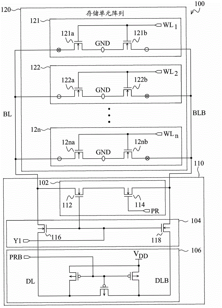
technical field [0001] The present invention relates to memory, and in particular to memory output circuits. Background technique [0002] figure 1 is a block diagram of at least a portion of a conventional memory circuit 100 . The memory circuit 100 includes a memory cell array 120 and a memory output circuit 110 . The memory cell array 120 includes a plurality of memory cells 121˜12n. The storage units 121˜12n are read-only memory (ROM) units and are coupled between a bit line and a bit bar line. Each memory cell 121˜12n includes two NMOS transistors and is coupled to a word line. For example, the memory cell 121 is coupled to the word line WL 1 and includes two NMOS transistors 121a and 121b, and the memory cell 122 is coupled to the word line WL 2 And includes two NMOS transistors 122a and 122b. The gates of the two NMOS transistors of the memory cells 121-12n are coupled to corresponding word lines, and the sources of the two NMOS transistors of the memory cells ...

Claims


Application Information

Patent Timeline
Patent Type & Authority Applications(China)
IPC IPC(8): G11C11/413
CPCG11C7/1057G11C7/1048G11C7/18G11C7/062G11C7/1069G11C7/12G11C11/413
Inventor 黄世煌
Owner MEDIATEK INC
Learn More