Fastening method for heating electronic device and radiating device

A technology of electronic devices and heat dissipation devices, which is applied in the field of device production technology for instant heat dissipation, can solve problems such as difficulties, high requirements for spring clip design and manufacturing, and high cost, and achieve the effects of reducing production costs, good stability, and convenient production

Active Publication Date: 2014-12-10
浙江易栋电子有限公司
View PDF3 Cites 0 Cited by
  • Summary
  • Abstract
  • Description
  • Claims
  • Application Information

AI Technical Summary

Problems solved by technology

[0004] like figure 2 As shown, using the spring clip 9 as a fixing method has the disadvantage that firstly, it must occupy a certain volume in order to generate pressure for elastic deformation, and the space occupied by this volume is not small; secondly, in applications that require high reliability and long life , the consideration of metal fatigue and corrosion resistance, the design consideration of ensuring the minimum working pressure in the working deformation of the shrapnel within all error ranges, and the consideration of the convenience and operability of placing the spring piece in assembly, lead to the design and manufacture of the spring clip High requirements and high cost
However, for applications with long-term vibration, how to ensure that the wedge-shaped part 10 is self-maintained in a fastened position is quite difficult; for applications that often face the working environment of thermal expansion and contraction in use, how to select the wedge-shaped part 10 It is also difficult for the material to have a relatively consistent thermal expansion coefficient between it and the fastened parts
like figure 2 Even if the wedge-shaped body is made of deformable engineering plastics, it is difficult to ensure that it will not loosen during use.

Method used


Image

  • Fastening method for heating electronic device and radiating device
  • Fastening method for heating electronic device and radiating device
  • Fastening method for heating electronic device and radiating device

Examples


example 1

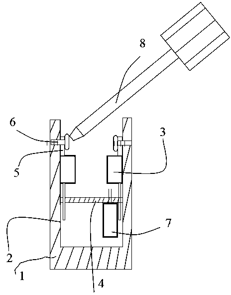
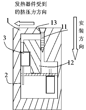
[0033] Example 1: If image 3 As shown, a deformable filler 12 is arranged on the outside of the heat-generating electronic device 3 opposite to the contact surface 2 of the heat dissipation device 1, and a threaded part 11 is fixed on the back of the filler 12. The contact surfaces 2 are parallel.

[0034] The threaded part 11 above can be a self-tapping screw, and the deformable filler 12 can be a plastic part.

[0035] Through the above method, the use of the deformable filler 12 to cooperate with the progress of the threaded part 11 in the fastening direction is achieved, so that the filler 12 is deformed when the threaded part 11 reaches the predetermined installation position, and the heat-generating electronic device 3 and the screw thread The part 11 forms a force component perpendicular to the traveling direction that presses the heat-generating electronic device 3 onto the heat-dissipating device 1 .

[0036] Wherein the threads of the threaded parts 11 are threade...


PUM


Abstract

The invention provides a fastening method for a heating electronic device and a radiating device, and relates to a production technology of an electronic device. The fastening method comprises the following steps of: enabling a filler to generate deformation when thread parts reach to a preset installing position by using the forwarding of the filler which is matched with the thread parts on the fastening direction of the thread parts, and component force with the direction perpendicular to the forwarding direction of the thread parts and can be used for extruding the heating electronic device onto the radiating device is formed to the heating electronic device and the thread parts. According to the fastening method, the collision problem between the space requirements of various devices caused by the other normal work requirements nearby parts to be cooled and the physical space requirements generated by fastening the parts to be cooled by using a normal method in the process of assembly can be solved, and the collision problem among the space requirements and the relative physical space requirements among the devices generated by improving the electrical performance in the application of electronic devices can be solved.

Description

technical field [0001] The invention relates to a production process of an electronic device, in particular to the technical field of a production process of a device that needs to dissipate heat from a heat-generating electronic device in real time. Background technique [0002] In the rapid development of modern electronic technology, the operating frequency of a single electronic chip or component is getting higher and higher, while the peripheral size of electronic products is getting smaller and smaller, which makes the problem of heat generation during work more and more a technical difficulty. For example, in order to keep the main CPU on the PC motherboard working normally, it is necessary to tailor a heat sink with a fan, and firmly fasten the heat sink to the flat surface above the CPU with screws; some even use small pumps and The liquid cooling method transfers the heat to the copper tube which is easy to install, and finally the fan exhausts the heat out of the ...

Claims


Application Information

Patent Timeline
Patent Type & Authority Patents(China)
IPC IPC(8): H05K7/20F16B39/22
Inventor 周斌欣
Owner 浙江易栋电子有限公司
Why Eureka
Try Eureka