Punching production line for punching circular tube type workpiece

A round tube-shaped production line technology, applied in the field of stamping production lines, can solve the problems of high labor intensity for operators, inability to process round tube-shaped workpieces in multiple passes, and high risk.

Inactive Publication Date: 2013-01-16
厦门锻压机床有限公司
View PDF8 Cites 43 Cited by
  • Summary
  • Abstract
  • Description
  • Claims
  • Application Information

AI Technical Summary

Problems solved by technology

The main problem of using one press machine to manually turn over and divide into multiple processing methods is that the processing efficiency is low, the labor intensity of the operator is high and the risk is high, when encountering different side positions of the circular tube-shaped workpiece and need to process different shapes, It is also necessary to change the mold frequently, and its processing efficiency is lower; through the processing method of multiple presses divided into multiple processes, because the workpiece needs to be continuously circulated, it is difficult to greatly improve the production efficiency, and at the same time it cannot solve the labor intensity of the operator. high risk problem
Although this multi-station continuous stamping machine can complete multiple stamping processes on one stamping machine, which can effectively improve production efficiency, the multi-station continuous stamping machine with this structure cannot perform multi-channel processing on the side of the round tubular workpiece.

Method used


Image

  • Punching production line for punching circular tube type workpiece
  • Punching production line for punching circular tube type workpiece
  • Punching production line for punching circular tube type workpiece

Examples


Embodiment Construction

[0027] The present invention will be described in further detail below in conjunction with the accompanying drawings and specific embodiments.

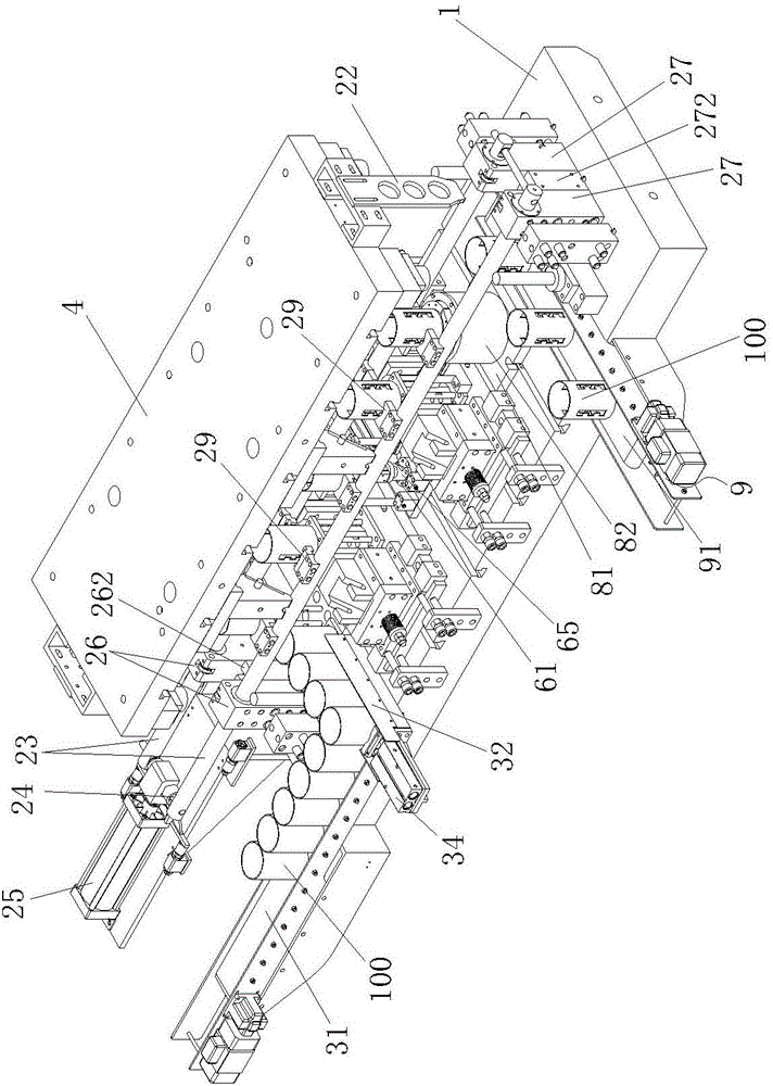
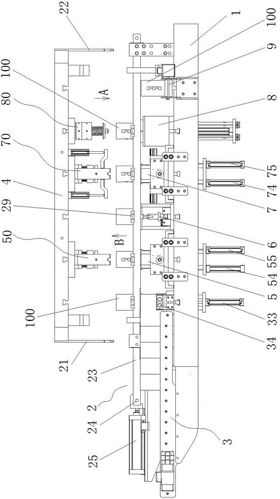
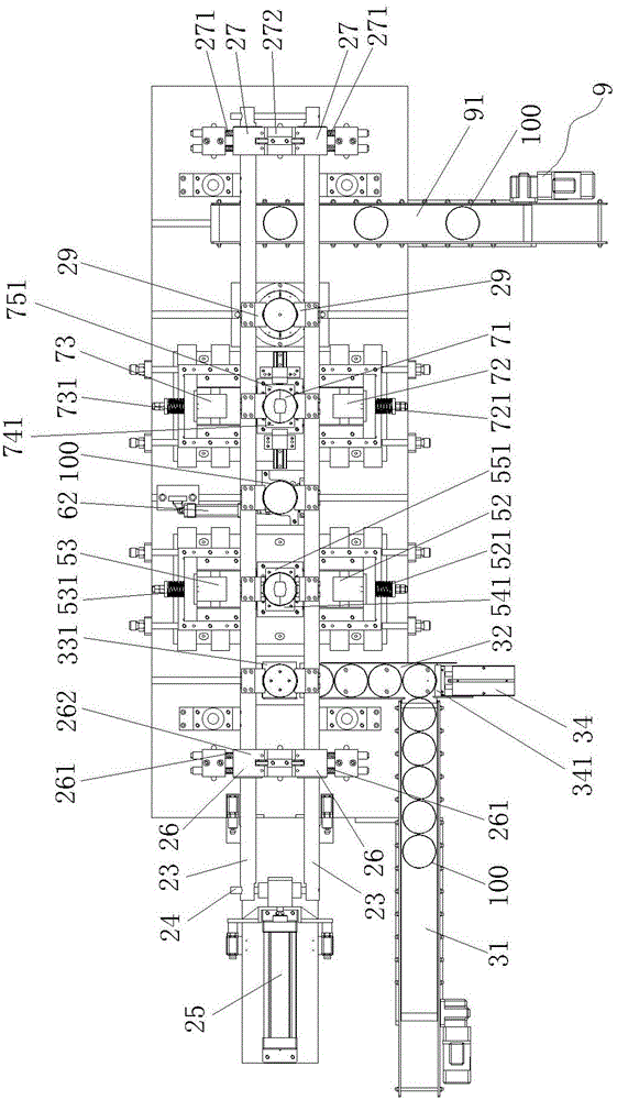
[0028] Figure 1 to Figure 10 As shown, a stamping production line for blanking circular tubular workpieces, including a press (only the workbench and the mounting seat of the slider are shown in the figure), and a circular tubular workpiece is installed on the workbench 1 of the press 100 is sequentially clamped from one station to the next station, the material transfer mechanism 2, the circular tube-shaped workpiece 100 is transported from the outside to the material transfer mechanism 2, and the feeding mechanism 3 is clamped at the initial position, and the slider 4 of the press The front support plate 21 and the rear support plate 22 are installed on the top to cooperate with the material transfer mechanism 2 to perform clamping and loosening actions;

[0029] On the press table 1 below the material shifting mechanism 2, the firs...


PUM


Abstract

The invention discloses a punching production line for punching a circular tube type workpiece. The punching production line comprises a press machine, wherein a moving mechanism and a feeding mechanism are assembled on an operating platform of the press machine, the moving mechanism sequentially clamps the circular tube type workpiece from one station to another station, and the feeding mechanism conveys the circular tube type workpiece from the outside to an initiation position from where the moving mechanism clamps; a first side punching lower die, a first circular tube type workpiece rotating mechanism, a second side punching lower die, a circular tube type workpiece shaping lower die and a discharging mechanism which discharges a circular tube type workpiece out of the operating platform of the press machine are at least assembled on the operating platform of the press machine below the moving mechanism; a first drive and a pressing component which are matched with the first side punching lower die and a second drive and the pressing component which are matched with the second side punching lower die are assembled on a sliding block of the press machine; and a press-in component which is matched with the shaping lower die is arranged. According to the punching production line, one press machine can be used for simultaneously carrying out multiple processing on the circular tube type workpiece, the production efficiency and automation degree are high, and the labor intensity and operation risk of operators are effectively reduced.

Description

technical field [0001] The invention relates to punching equipment, in particular to a punching production line for punching round tubular workpieces. Background technique [0002] When the side of a circular tube-shaped workpiece needs to be processed in multiple positions, there are usually two processing methods, one is to manually turn it over on one press and divide it into multiple processes; the other is to divide it into multiple processes through multiple presses processing. The main problem of using one press machine to manually turn over and divide into multiple processing methods is that the processing efficiency is low, the labor intensity of the operator is high and the risk is high, when encountering different side positions of the circular tube-shaped workpiece and need to process different shapes, It is also necessary to change the mold frequently, and its processing efficiency is lower; through the processing method of multiple presses divided into multipl...

Claims


Application Information

Patent Timeline
Patent Type & Authority Applications(China)
IPC IPC(8): B21D22/02B21D43/10B21D43/02B21D45/06
Inventor 廖吉林曾智勇张远杨青黄中坤苏兰
Owner 厦门锻压机床有限公司
Why Eureka
Try Eureka