Direct-current ventilation four-stroke engine
A four-stroke engine and four-stroke technology, applied to engine components, combustion engines, machines/engines, etc., can solve problems such as excessive scavenging, high heat load, and large flow resistance, and achieve high efficiency, small heat load, and smooth flow The effect of low resistance
- Summary
- Abstract
- Description
- Claims
- Application Information
AI Technical Summary
Problems solved by technology
Method used
Image
Examples
Embodiment 1
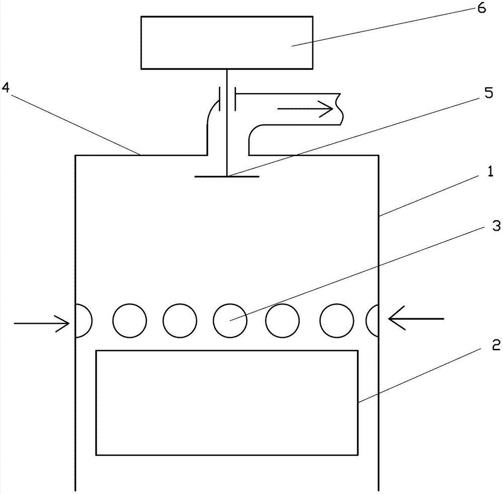
[0035] Such as figure 1 The shown direct current ventilation four-stroke engine includes a cylinder 1 and a piston 2, the piston 2 is arranged in the cylinder 1, the piston 2 cooperates with the cylinder 1, and on the side wall of the cylinder 1 Air inlet 3 is established, and described air inlet 3 is set as several, and exhaust valve 5 is established on described cylinder 1, and described exhaust valve 5 is subjected to described DC ventilation four-stroke engine to press vacuum charging stroke- —compression stroke—expansion power stroke—exhaust stroke The exhaust control mechanism 6 working in the four-stroke working mode is controlled, and the exhaust valve 5 is arranged on the cylinder head 4 of the cylinder 1 .
[0036] The specific working process is as follows: when the exhaust stroke of the last cycle of the piston 2 is over, the engine starts the vacuum charging stroke (that is, equivalent to the suction stroke of a traditional four-stroke engine), and at this time t...
Embodiment 2
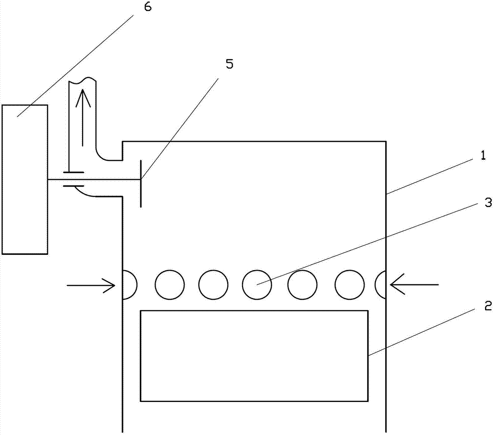
[0038] Such as figure 2 The difference between the direct-flow ventilation four-stroke engine shown in Embodiment 1 is that the exhaust valve 5 is arranged on the side wall of the cylinder 1 corresponding to the top dead center of the piston 2 .
Embodiment 3
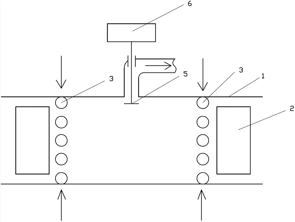
[0040] Such as image 3 The difference between the straight-flow ventilation four-stroke engine shown in Embodiment 1 is that two pistons 2 are arranged oppositely in one cylinder 1, and the piston 2 is arranged along the side wall of the cylinder 1. Two groups of intake ports 3 are arranged in the axial direction of the cylinder, and the exhaust valve 5 is arranged on the side wall of the cylinder 1 between the two groups of intake ports 3 .
PUM
 Abstract
Description
Claims
Application Information
 - R&D
- Intellectual Property
- Life Sciences
- Materials
- Tech Scout
- Unparalleled Data Quality
- Higher Quality Content
- 60% Fewer Hallucinations
Browse by: Latest US Patents, China's latest patents, Technical Efficacy Thesaurus, Application Domain, Technology Topic, Popular Technical Reports.
© 2025 PatSnap. All rights reserved.Legal|Privacy policy|Modern Slavery Act Transparency Statement|Sitemap|About US| Contact US: help@patsnap.com


